The answer is the M and H series diodes are much more efficient than the A series diodes. They have an extra bond wire and a larger die. Most all M and H diodes can hit 2W+ with a single element lens and 1.8A current.
")
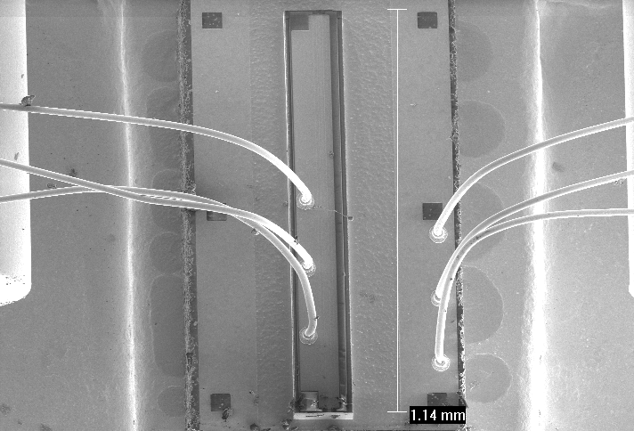
That extra bond wire is not part of the anode nor cathode, and serves no
additional function for current delivery. Now if there were 2 additional routed
to + / - points of the die, you could safely assume that more current could be
delivered. Though in this case its not.
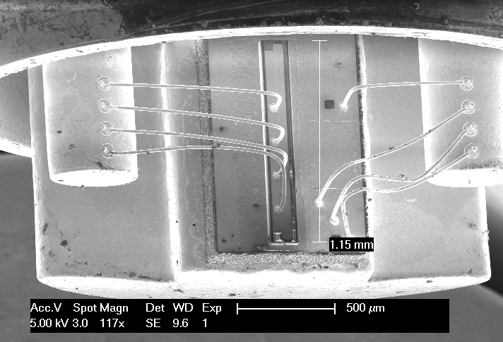
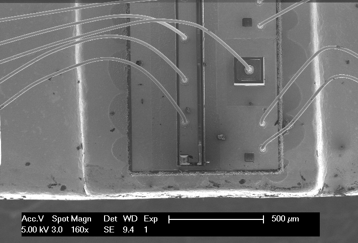
Also, as PBD pointed out, its the submount which is larger, not the die.. The submount
is the larger square pad which the die is mounted to. The die itself is the long
thin line running down the center. The only other difference I would assume is
possibly a slight increase in the flow of heat into the body of the diode.
In neutral ground diodes, the submount is only thermally conductive, so in this
case, it being larger, will also not have any affect on power to the die..
EDIT* Just to save confusion, I was referring to the 'extra' bond wire to the single
extra, I misread the quoted post as if you were referring to that one. Need to read 3x
when posting at such a late hour.. :undecided:


")