benmwv
0
- Joined
- Sep 10, 2010
- Messages
- 1,380
- Points
- 48
How would you like free boost driver designs?! :drool:
Though I can't control anyone's actions, I would appreciate it if anyone wishing to sell this circuit would get permission from rhd or me first.
This is a project that I have been working on with RHD for a pretty long time and it is finally ready!
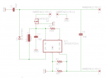
Here it is(R6 R9):
(Schematic)

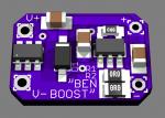
(Board)


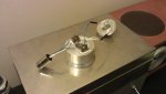
(Don't be fooled by those "design pictures" this thing is real! Rhd is going to post some nice pics on the first reply to this post)
Rhd has dubbed it "The Ben Boost" and I think its a pretty good name
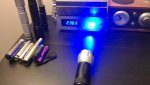
So this is a boost driver based on the lm3410. Single li-ion or 2x/3x alkaline/nimh ONLY. It is meant to drive diodes with a Vf greater than the input voltage, like 445 and 405 diodes. It has been tested at a little under 1.2A on a 445nm diode and worked great, it may go a bit higher but I wouldn't expect anything over 1.3A. These drivers can also be paralleled to get higher currents like 1.8A. Rhd has a build using two of these drivers in parallel, see it in the next post!
The driver can boost to quite high voltages (28v IIRC) , so you could run two or three reds in series with this driver if you wanted. But remember, with a higher output voltage your maximum possible output current will decrease.
Current is calculated by: I (in Amps) = 0.19 / Rset (in Ohms)
Here is a table of values:
R1,R2,Current (ma)
1R0,xxx,190
R75,xxx,253
1R0,1R0,380
1R0,R75,442
R75,R75,507
1R0,R50,570
R75,R50,633
R50,R50,760
R33,R75,830
R30,R75,888
R33,R50,955
R50,R30,1013
R33,R33,1151
R33,R30,1210
R30,R30,1267
(Each of the resistors above you can get on digikey in 1/3W 0805 in 1 part quantity for $0.35 from the Susumu manufacturer)
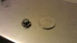
This driver is 9.5mm x 13.8mm.
Now here's kicker: total part cost is about FIVE bucks! That means you could make two of these and parrallel them to 1.8A for about $10 (compared to $50-60 to do the same thing with flexdrives :eg")
The release version of this driver has reverse polarity protection which isn't in the version in Rhd's pics. We added reverse polarity protection because the first three working prototypes of this driver died by shorting, mechanical damage, and reverse polarity so we fixed what we could. I assure you all of this was done on purpose as testing to see what extremes the driver can handle and they weren't mistakes at all :na:
BIG Update!
I feel confident the "Benboost Mini" is ready. This is a smaller, and much better version of the benboost. The LD+/- cap has been completely removed, now there a 2x 22uf caps from LD+ to GND. It uses the LLP 3x3 version of the lm3410 which has a thermal pad for heat transfer. There is a pad on the bottom of the board directly beneath the lm3410 where a heatsink can be soldered in. With just a small cube of copper on this pad and no other heatsink the driver must be run very hard to cause it to overheat. Since the heatsinking is so much better we can now utilize the full switch current of the driver without overheating. These drivers can handle 1.7A from 4.2v (full battery) in down to at least 4v, and most can go lower than that. For example, I have one with a max switch current of 2.6A (200ma below the chips average of 2.8A) and it can do 1.7A down to around 3.9V. An average 2.8A switch current chip should be able to go down to 3.8v or 3.7v. I feel confident saying all can provide 1.4A into a 445 diode over the entire discharge of a li-ion, many should be able to do 1.5a or 1.6A.
You guys should definitely try these out, they are WAY better than the original! Parts list below in the changelog, files at the bottom of this post.
More info, including oscope tests in the is post:
http://laserpointerforums.com/f67/f...iver-tested-working-71433-47.html#post1104257
~~~~~~~~~~~~~~~~~~~~~~~~~~~~~~~~~~~~~~~~~~~~~~~~~~
Feeling generous?
Do you like this driver? Has it helped you?
Make everyone jealous by getting your name on the supporters list!
I've got a couple new designs in my head that could use some funding

BenBoost Supporters: Me, RHD, Mohrenberg, Anthot, Gillza, Blord, Wee40811
~~~~~~~~~~~~~~~~~~~~~~~~~~~~~~~~~~~~~~~~~~~~~~~~~~
Warning: I am recommending everyone to use 22uf caps, and leave off C3. The cap was causing some oscillations in the output. It will be taken out on future design updates. With these changes it is safe to use this on sensitive diodes such as 12x.
Here is the parts list:
IC1:
LM3410 - $1.58: LM3410XMFE/NOPB | LM3410 Series 5.5 V 1.6 MHz Constant Current Boost and SEPIC LED Driver SOT-23-5 | NATIONAL SEMICONDUCTOR - Future Electronics
OR
LM3410 - $3.20: LM3410XMF/NOPB National Semiconductor | LM3410XMFCT-ND | DigiKey
Q1:
P-channel mosfet - $0.79: Digi-Key - SI3473CDV-T1-GE3CT-ND (Manufacturer - SI3473CDV-T1-GE3)
R3:
100k 0603 - $0.05: Digi-Key - P100KHCT-ND (Manufacturer - ERJ-3EKF1003V)
R1, R2:
Set Resistors (0805) - VARIES
L1:
Inductor - $0.66: Digi-Key - 587-2001-1-ND (Manufacturer - NR8040T100M)
C1, C2:
2x 22uF 0805 Caps - $0.77: C2012X5R1C226K TDK Corporation | 445-6797-1-ND | DigiKey
D1:
Shottky - $0.46: PMEG2020EH,115 NXP Semiconductors | 568-4118-1-ND | DigiKey
PCB - $0.31 : OSH Park ~ Welcome
~~~~~~~~~~~~~~~~~~~~~~~~~~~~~~~~~~~~~~~~~~~~~~~~~~
Changelog
R6 R9: Original posted design. Has reverse polarity protection, 0805 caps, No OVP.
R6 R9 Round v6: Originally posted design (0805 caps, no OVP) on a 16.5mm board to go right into most flashlight pills, with battery contacts on the bottom.
R6 R10: Replaced 0805 caps with 1206 caps (not as tall).
C1, C2:
2x 22uf 1206 Caps - $0.60: EMK316BJ226ML-T Taiyo Yuden | 587-1433-1-ND | DigiKey
R6 R11 OVP2: Added OVP (over-voltage protection) driver can now be powered up with no load connected. (still has 1206 caps)
D2:
12v Zener - $0.27: Digi-Key - 568-6279-1-ND (Manufacturer - BZX384-C12,115)
R4:
100 ohm 0603 - $0.02: Digi-Key - P100GCT-ND (Manufacturer - ERJ-3GEYJ101V)
Benboost Mini v5:
IC1:
LM3410 - $3.20: LM3410XSD/NOPB National Semiconductor | LM3410XSDCT-ND | DigiKey
Q1:
P-channel mosfet - $0.76: SI3493BDV-T1-E3 Vishay Siliconix | SI3493BDV-T1-E3CT-ND | DigiKey
R3:
100k 0603 - $0.10: ERJ-3EKF1003V Panasonic Electronic Components | P100KHCT-ND | DigiKey
R1, R2:
Set Resistors (0805) - VARIES
L1:
Inductor - $0.31: NR5040T4R7N Taiyo Yuden | 587-2373-1-ND | DigiKey
C1, C2, C3:
3x 22uF 1206 Caps - $0.60: EMK316BJ226ML-T Taiyo Yuden | 587-1433-1-ND | DigiKey
D1:
Shottky - $0.45: PMEG3030EP,115 NXP Semiconductors | 568-6761-1-ND | DigiKey
~~~~~~~~~~~~~~~~~~~~~~~~~~~~~~~~~~~~~~~~~~~~~~~~~~
EAGLE board files are attached!!!!!!! [For EAGLE 6]
Though I can't control anyone's actions, I would appreciate it if anyone wishing to sell this circuit would get permission from rhd or me first.
This is a project that I have been working on with RHD for a pretty long time and it is finally ready!
Here it is(R6 R9):
(Schematic)
(Board)
(Don't be fooled by those "design pictures" this thing is real! Rhd is going to post some nice pics on the first reply to this post)
Rhd has dubbed it "The Ben Boost" and I think its a pretty good name
So this is a boost driver based on the lm3410. Single li-ion or 2x/3x alkaline/nimh ONLY. It is meant to drive diodes with a Vf greater than the input voltage, like 445 and 405 diodes. It has been tested at a little under 1.2A on a 445nm diode and worked great, it may go a bit higher but I wouldn't expect anything over 1.3A. These drivers can also be paralleled to get higher currents like 1.8A. Rhd has a build using two of these drivers in parallel, see it in the next post!
The driver can boost to quite high voltages (28v IIRC) , so you could run two or three reds in series with this driver if you wanted. But remember, with a higher output voltage your maximum possible output current will decrease.
Current is calculated by: I (in Amps) = 0.19 / Rset (in Ohms)
Here is a table of values:
R1,R2,Current (ma)
1R0,xxx,190
R75,xxx,253
1R0,1R0,380
1R0,R75,442
R75,R75,507
1R0,R50,570
R75,R50,633
R50,R50,760
R33,R75,830
R30,R75,888
R33,R50,955
R50,R30,1013
R33,R33,1151
R33,R30,1210
R30,R30,1267
(Each of the resistors above you can get on digikey in 1/3W 0805 in 1 part quantity for $0.35 from the Susumu manufacturer)
This driver is 9.5mm x 13.8mm.
Now here's kicker: total part cost is about FIVE bucks! That means you could make two of these and parrallel them to 1.8A for about $10 (compared to $50-60 to do the same thing with flexdrives :eg
The release version of this driver has reverse polarity protection which isn't in the version in Rhd's pics. We added reverse polarity protection because the first three working prototypes of this driver died by shorting, mechanical damage, and reverse polarity so we fixed what we could. I assure you all of this was done on purpose as testing to see what extremes the driver can handle and they weren't mistakes at all :na:
BIG Update!
I feel confident the "Benboost Mini" is ready. This is a smaller, and much better version of the benboost. The LD+/- cap has been completely removed, now there a 2x 22uf caps from LD+ to GND. It uses the LLP 3x3 version of the lm3410 which has a thermal pad for heat transfer. There is a pad on the bottom of the board directly beneath the lm3410 where a heatsink can be soldered in. With just a small cube of copper on this pad and no other heatsink the driver must be run very hard to cause it to overheat. Since the heatsinking is so much better we can now utilize the full switch current of the driver without overheating. These drivers can handle 1.7A from 4.2v (full battery) in down to at least 4v, and most can go lower than that. For example, I have one with a max switch current of 2.6A (200ma below the chips average of 2.8A) and it can do 1.7A down to around 3.9V. An average 2.8A switch current chip should be able to go down to 3.8v or 3.7v. I feel confident saying all can provide 1.4A into a 445 diode over the entire discharge of a li-ion, many should be able to do 1.5a or 1.6A.
You guys should definitely try these out, they are WAY better than the original!
Parts list below in the changelog, files at the bottom of this post.More info, including oscope tests in the is post:
http://laserpointerforums.com/f67/f...iver-tested-working-71433-47.html#post1104257
~~~~~~~~~~~~~~~~~~~~~~~~~~~~~~~~~~~~~~~~~~~~~~~~~~
Feeling generous?
Do you like this driver? Has it helped you?
Make everyone jealous by getting your name on the supporters list!
I've got a couple new designs in my head that could use some funding
BenBoost Supporters: Me, RHD, Mohrenberg, Anthot, Gillza, Blord, Wee40811
~~~~~~~~~~~~~~~~~~~~~~~~~~~~~~~~~~~~~~~~~~~~~~~~~~
Warning: I am recommending everyone to use 22uf caps, and leave off C3. The cap was causing some oscillations in the output. It will be taken out on future design updates. With these changes it is safe to use this on sensitive diodes such as 12x.
Here is the parts list:
IC1:
LM3410 - $1.58: LM3410XMFE/NOPB | LM3410 Series 5.5 V 1.6 MHz Constant Current Boost and SEPIC LED Driver SOT-23-5 | NATIONAL SEMICONDUCTOR - Future Electronics
OR
LM3410 - $3.20: LM3410XMF/NOPB National Semiconductor | LM3410XMFCT-ND | DigiKey
Q1:
P-channel mosfet - $0.79: Digi-Key - SI3473CDV-T1-GE3CT-ND (Manufacturer - SI3473CDV-T1-GE3)
R3:
100k 0603 - $0.05: Digi-Key - P100KHCT-ND (Manufacturer - ERJ-3EKF1003V)
R1, R2:
Set Resistors (0805) - VARIES
L1:
Inductor - $0.66: Digi-Key - 587-2001-1-ND (Manufacturer - NR8040T100M)
C1, C2:
2x 22uF 0805 Caps - $0.77: C2012X5R1C226K TDK Corporation | 445-6797-1-ND | DigiKey
D1:
Shottky - $0.46: PMEG2020EH,115 NXP Semiconductors | 568-4118-1-ND | DigiKey
PCB - $0.31 : OSH Park ~ Welcome
~~~~~~~~~~~~~~~~~~~~~~~~~~~~~~~~~~~~~~~~~~~~~~~~~~
Changelog
R6 R9: Original posted design. Has reverse polarity protection, 0805 caps, No OVP.
R6 R9 Round v6: Originally posted design (0805 caps, no OVP) on a 16.5mm board to go right into most flashlight pills, with battery contacts on the bottom.
R6 R10: Replaced 0805 caps with 1206 caps (not as tall).
C1, C2:
2x 22uf 1206 Caps - $0.60: EMK316BJ226ML-T Taiyo Yuden | 587-1433-1-ND | DigiKey
R6 R11 OVP2: Added OVP (over-voltage protection) driver can now be powered up with no load connected. (still has 1206 caps)
D2:
12v Zener - $0.27: Digi-Key - 568-6279-1-ND (Manufacturer - BZX384-C12,115)
R4:
100 ohm 0603 - $0.02: Digi-Key - P100GCT-ND (Manufacturer - ERJ-3GEYJ101V)
Benboost Mini v5:
IC1:
LM3410 - $3.20: LM3410XSD/NOPB National Semiconductor | LM3410XSDCT-ND | DigiKey
Q1:
P-channel mosfet - $0.76: SI3493BDV-T1-E3 Vishay Siliconix | SI3493BDV-T1-E3CT-ND | DigiKey
R3:
100k 0603 - $0.10: ERJ-3EKF1003V Panasonic Electronic Components | P100KHCT-ND | DigiKey
R1, R2:
Set Resistors (0805) - VARIES
L1:
Inductor - $0.31: NR5040T4R7N Taiyo Yuden | 587-2373-1-ND | DigiKey
C1, C2, C3:
3x 22uF 1206 Caps - $0.60: EMK316BJ226ML-T Taiyo Yuden | 587-1433-1-ND | DigiKey
D1:
Shottky - $0.45: PMEG3030EP,115 NXP Semiconductors | 568-6761-1-ND | DigiKey
~~~~~~~~~~~~~~~~~~~~~~~~~~~~~~~~~~~~~~~~~~~~~~~~~~
EAGLE board files are attached!!!!!!! [For EAGLE 6]
Attachments
-
![LD Boost Driver lm3410 R6 (Fork Again) R9 [FRONT].PNG](/data/attachments/23/23349-e137f5d68474f9e5a73c40d4375d3ddd.jpg?hash=4Tf11oR0-e) LD Boost Driver lm3410 R6 (Fork Again) R9 [FRONT].PNG83 KB · Views: 12,922
LD Boost Driver lm3410 R6 (Fork Again) R9 [FRONT].PNG83 KB · Views: 12,922 -
![LD Boost Driver lm3410 R6 (Fork Again) R9 [BACK].PNG](/data/attachments/23/23350-36afd54c79d9e6e25a82053c03f38a50.jpg?hash=Nq_VTHnZ5u) LD Boost Driver lm3410 R6 (Fork Again) R9 [BACK].PNG35.7 KB · Views: 12,161
LD Boost Driver lm3410 R6 (Fork Again) R9 [BACK].PNG35.7 KB · Views: 12,161 -
LD Boost Driver lm3410 R6 (Fork Again) R9.zip7.8 KB · Views: 533
-
 LD Boost Driver lm3410 FINAL SCHEMATIC.PNG23.5 KB · Views: 15,612
 -
LD Boost Driver lm3410 R6 (Fork Again) R10.zip8.1 KB · Views: 346
-
LD Boost Driver lm3410 R6 R11 - OVP2.zip7.7 KB · Views: 418
-
LD Boost Driver lm3410 R6 R9 - Round v6.zip6.7 KB · Views: 458
-
LD Boost Driver lm3410 LLP3x3 v5.zip34.2 KB · Views: 424
Last edited:


")