Welcome to Laser Pointer Forums - discuss green laser pointers, blue laser pointers, and all types of lasers

LPF Donation via Stripe | LPF Donation - Other Methods

Links below open in new window

ArcticMyst Security by Avery

Planning DIY TPS63000 based driver

Rafa

0
Joined
Feb 4, 2010
Messages
437
Points
0
Think adding a .1uF bypass cap to the FB via would help?
4357-fbbyp.png

I don't think that will help.

If you see lava's design (BTW Lava, we are NOT trying to copy you. We
just want to callenge ourselves making good drivers.) the capacitor is in series
with the amp.


Joined
Jun 30, 2008
Messages
286
Points
0
I don't think that will help.

If you see lava's design (BTW Lava, we are NOT trying to copy you. We
just want to callenge ourselves making good drivers.) the capacitor is in series
with the amp.

That's impossible, a series capacitor blocks the direct current, only letting alternate current to pass through. It's very hard to tell how lava does it without having an actual lavadrive in our hands. But the capacitor isn't in series with the FB input, that's for sure.

To jib: I told you I made some previous designs with op-amps. Linear technology provides some spice software that is pretty accurate, and there you can simulate this kind of circuits. That idea of the capacitor also came to me, and it works. Really stabilizes the output... but... it has some downside, and that downside is that the capacitor needs to be charged and in the time it takes to charge the cap, the current just climbs up and up, thus having a current spike that would likeky kill or damage the diode.

For sure you can use lower value capacitors and take advantage of the soft start features of the IC's to avoid the current spike, but simulator told me that, using capacitor values with a charge time lower than soft start duration didn't totally stabilize the output, so there's a compromise.

Just in case, I think that the highest value capacitor I tried were 10nF, and that was waaaay too much. Try it if you want with a dummy load and set the o-scope to trigger and capture the transient (should be around 0.X milliseconds or less).
I currently don't know how the optimal solution would be, maybe the next semester I learn how to design drivers more properly, as I have a subject of heavy analog electronics.... It surely requires solving some differential equations and adding capacitors in unsuspected places xD.
 

jib77

0
Joined
Jun 19, 2010
Messages
718
Points
0
Man the pads on these XFL inductors SUCK! I even tried solder wicking the excess off and it was still sliding around during reflow. WTF!?

Anyways ... I got it working with the 2.2uH, kinda. It only works with input voltage of 1.6V to 2.2V. With a 4V dummy load it pulls 350mA @ 1.6V and 500mA @ 2.2V. As I slowly bring the fine adjust of the PSU to 2.3V it promptly shuts down. There was no perceivable heat being generated. Any Ideas?
 

jib77

0
Joined
Jun 19, 2010
Messages
718
Points
0
Well ... dammit ... I put the output filter caps on the wrong side of the set resistors. So basically Im not filtering the VOUT from the TPS63020, this cant be good. (They are in the correct place on the TPS63000 board) :rolleyes:
 

drlava

0
Joined
Mar 7, 2007
Messages
1,152
Points
0
I don't think that will help.

If you see lava's design (BTW Lava, we are NOT trying to copy you. We
just want to callenge ourselves making good drivers.) the capacitor is in series
with the amp.

If you want to challenge yourself and not copy, you don't need to look at my design at all :)
So far what I see is running into a challenge and quickly people go hmm, how did HE do it? Well, if you're going to do an honest design you're best off not even talking about or looking at mine.
 

jib77

0
Joined
Jun 19, 2010
Messages
718
Points
0
Re: Planning DIY TPS630x0 based driver

ITS ALIVE!!! :)

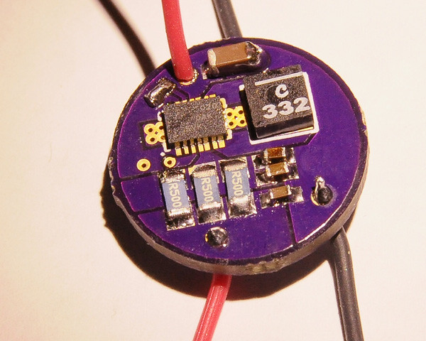
So far I tested with 3 x 0.5Ω set resistors which yield 350mA max. I plan on stacking two more 0.5's to see if I get 2A+.

The 100K pot only gives a 90 mA range at the 350mA current setting, I can turn it down to 260mA.

The pads in square marked "byp" can be connected to bypass the pot.


Blob on top left is bridging the Enable pin to VIN ... Its a 0402 sized pad, remove this blob and it can be used for TTL. I still cant belive how much that inductor floats around during reflow instead of being "sucked" to the pads like everything else :/

 
Last edited:
Joined
Jun 30, 2008
Messages
286
Points
0
Great it worked! But don't forget to make some startup transient analysis!
You don't want to stress your diodes with startup current spikes!.

The capacitor filters the Vfb, but at the expense of a likely startup current spike because the capacitor needs to be charged to Vfb and that takes time.
 
Joined
Aug 7, 2010
Messages
2,086
Points
0
very interesting. I ordered another a140.. I need one of these (with the 5 x 0.5Ω ofc)..
waiting for news~
 

jib77

0
Joined
Jun 19, 2010
Messages
718
Points
0
Ok, I finally got some time to play. 5x0.5Ω = 0.0125 for 2A ... no difference in current, still 350mA max. WTF!? Turning up the pot resistance yields *higher* current, with the lowest current at 0Ω on the pot(and pot taken out of circuit).

So I though I might have messed up and built a second one board ... this time 2x0.33Ω + 1x0.1Ω for a total of 0.0143Ω which should yield 1.745A ... it only does 510mA. Again WTF!?

This was all with a PSU set at 3.9V with a 4V test load. The PSU was indicating 0.8A-1.2A of current draw. Ill test with a 26650 battery when I get a chance.

 
Joined
Dec 23, 2010
Messages
561
Points
0
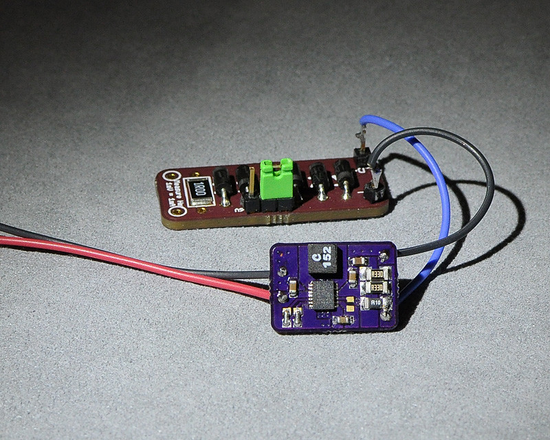
hmm kinda old thread but in case anyone was wondering, there is a commercially available tps61030 boost driver available sized no bigger than a flex, and limited to 1amp (IC limit) for 12 bucks. kinda interesting, and despite being a LED driver, it works well with a 445, will try with a 12x 405 as money allows :D. link to THREAD
 
Joined
Dec 23, 2010
Messages
561
Points
0
DO PLEASE!!! :bowdown:

I dont mind hooking up LED drivers to a 445 but theres something about a 50 dollar, sled extracted 12x 405 that makes me cringe when i think about using a "non-standard" driver. If your version of a 61030 IC is 100% safe for even picky 12x's, then i'd :drool: all over it. 94% efficient boost driver...


I am Currently working on a boost driver with that chip.;)
 

HIMNL9

0
Joined
May 26, 2009
Messages
5,318
Points
0
Just as idea ..... are you sure you're using inductors with enough saturation current ?

When i made some tests with these chips, i discarded them cause they was very "picky" about the inductors ..... not just the values, i was using 2.7 and 3.3 uH, but overall about current saturation of the coil itself (maybe now are available better and smaller inductors with higher saturation currents, anyway ..... also, here is difficult to get the right components, so i had to experiment with that what i had at hands :p).
 

jib77

0
Joined
Jun 19, 2010
Messages
718
Points
0
Well I tried 2.7 and 3.3 with the inductors TI recommends. The TPS61000 works great, but the TPS 63020 does not ... I think with my resistor settings over 1.5A its going into a limited current mode. Im convinved the 63020 can not do over 1.5A at 4V, I just havn't had time to prove it.


Top