1st:
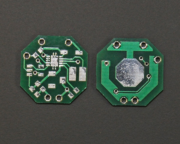
PCB is WRONG. You're dealing with high currents switching at high frequency. YOU MUST ground to a point or solid ground "plane". Using small traces between leads of components and then to the ground point is a fail, as the traces between component's pads act as parasitic inductances... and we don't want that.
Also, the thermal pad MUST be soldered to solid copper. There must be some copper area surrounding that pad so the IC can get rid of the heat generated inside.
Also, you must make power traces as wide and short as possible, less than 5mm long or so.
And that SPECIALLY applies to the feedback trace. There's a high precission comparator inside the chip taking samples of the voltage in that pin at very high speed. That trace MUST be wide and short, or else, any induced noise would cause inestabilities and ripple in the integrated circuit.
That's not a power trace, but a high frequency analog trace, which also need to be wide and short.
2º The coil is wrong. Dunno what coil you're using but it looks way tooo small. Small coils have high ESR and low saturation current. During startup, there's a current spike that the coil MUST handle without saturating, or else, the driver might not start. Just get a bigger, more massive coil with some serious ferrite core. Something with less than 0.1ohm of series resistance and with saturation currents around 2-2.5A should be fine. You should find those in 5x5 or even 4x4mm packages.
3º The design itself might be wrong. I've tried to make designs like yours with high side current sensing using a differential currtent sensing amplifier and all of them went seriously wrong. They just weren't fast enough to be able to "update" themselfs at the speeds required by the regulator IC, so it didn't stabilize and the current just oscillated between the one it was supposed to be set to and the max current the driver could deliever. A plain and complete fail. Adding a capacitor solved the problem but made the driver go "full power" until the capacitor charged, which happened in less than a millisecond, but enough to kill a diode with a very high current spike.
And yeah, I tried some very fast amplifiers.
4º The sensing shunt resistor will be a very low value one, in the range of 0.1 ohms or so. Try finding potentiometers of those values. You can't adjust that resistor. A better way is to add a potentiometer as a voltage divider in the output of the amplifier.
If you want any design help, or any example of how a PCB for one of these must be designed, just ask for it.


 ).
).