Welcome to Laser Pointer Forums - discuss green laser pointers, blue laser pointers, and all types of lasers

Buy Site Supporter Role (remove some ads) | LPF Donations

Links below open in new window

FrozenGate by Avery

Planning DIY TPS63000 based driver

Man this thread has really moved along. :gj: and congratulation on getting it up to 1.14amps.

The joints look perfect. Very Clean. You really got that heat station down now. :beer:


ahahha yeah :p
well, I have thinked about the cent coin. but I think the pot is a MUST :(
so.. when the "evaluation boards" will be available ? :D
 
ahahha yeah :p
well, I have thinked about the cent coin. but I think the pot is a MUST :(
so.. when the "evaluation boards" will be available ? :D

I dont know ... part of me wants to test for 1.6A and the other tells me to do a TPS63020 board: :drool:

 
Last edited:
Ok, time to recoup some R&D costs. I have one driver set for 758mA and two set for 1.2A available. $20 shipped(US). PM me.

1.2A #1 -- SOLD - Vaporizer [paid] -- shipped
1.2A #2 -- SOLD - gillza[paid] -- shipped
758mA -- Keeping it.
 
Last edited:
I'll let others have 1st shot, but I'm sending a PM to help cover the R&D in case no one jumps. R&D gets expensive, been there many times. Not just in laser stuff.
 
About resistors and amplifier gain: a gain of 5 or 20 doesn't make a big difference, as low value resistors are still needed, and you don't have pots of those values. To make it adjustable, you'd have to do this:

dibsujo.png

@Erdabyz ... with 20 gain, is 100KΩ what you recommend for the trim pot in this configuration?
How does the pot effect the output current ... higher R == higher I or is it inverse?
Think this layout for the pot will work?

4133-schem-trim.png

4134-layout-trim.png
 
Last edited:
@Erdabyz ... with 20 gain, is 100KΩ what you recommend for the trim pot in this configuration?
How does the pot effect the output current ... higher R == higher I or is it inverse?
Think this layout for the pot will work?

4133-schem-trim.png

4134-layout-trim.png

Hmm the pot's value should be calculated considering both INA193 output impedance and TPS63000's feedback input impedance. What experience and logic tells me is that TPS63000's FB input would be the gate of a MOS transistor, so that impedance should be in the tens of Mohms range, and that INA193's output impedance would be in the ohms range, so yeah, anything in the 10K's or 100k's should be fine, or so I guess.

Higher R means lower I. The pot's value should be high enough for not loading the INA in excess, but low enough to be "negligible" compared to the FB's input impedance, to get a precise and linear control.

And yeah, that's the layout i'd use if i'd keep that driver for me, but if you're gonna sell it, you must add a limiting resistor between the low terminal of the potentiometer and ground, because if you turn the potentiometer to its lower limit the current will increase and increase until the regulator can't satisfy your demands anymore and will enter a unstable and extreme state. So you must add a resistor there so that even if you turn the pot so much that the center tap has 0ohms to the low terminal, there's a resistor between there and ground to make a voltage divider with the whole potentiometer resistance that leads to the maximum current you want it to give (in your case it should be somewhere around 1.2A)


BTW, my 63020 design has turned out to be an epic failure, but I think it's because I sort of damaged a component. It has a HORRIBLE ripple and efficiency and as a result it overheats as hell and it's useless. I'll do another board, and finally test yours this friday.
 
Last edited:
I got the boards in for my TPS63020 design the other day, but as usual Mouser was out of a certain TI IC until a few hours ago. I wasn't expecting the boards to come in so soon anyways. :banghead:

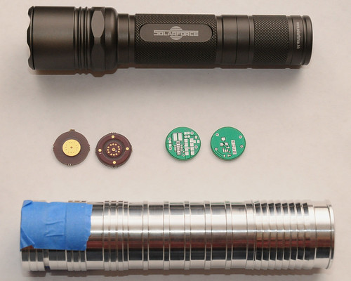
jib77, I can send you one of the pannelized boards if you're interested.

 
What value R for the low side resistor?
What about tying both the low side and tap to the FB?


Got it, thanks!

Tying the low side and tap together would be OK too. What you want is a voltage divider with a fixed value low resistor to limit the max current.

The value of that resistors depends on the value of the sense resistor.

For example, let's say you want to make an adjustable driver from 400mA to 1.2A. With the potentiometer set to its highest position, the voltage from the INA would pass unaltered to the FB pin, as the high side and tap of the pot get directly connected, meaning that you should calculate your sense resistor for getting 500mV from the INA at 400mA's (as if you were calculating the sense resistor for a fixed 400mA current).

Then, with that value of resistor, you have to calculate how much voltage would drop in it at the maximum current you want from the driver. For 400mA's, the sense resistor would be 0.0625 ohms. With that resistor, you get a voltage drop of 1.2*0.0625 = 0.075 volts, and given that INA193 has a voltage gain of 20, you'd get 20*0.075 = 1.5volts (oh, surprise xD) at INA's output. At max current, you would have your potentiometer on its lowest position, meaning that you'd have a voltage divider made with the whole pot's resistance as the high resistor, and your limiting resistor as your low resistor. Calling the limiting resistor Rlim, and pot's resistance Rpot, the ecuation to get it would be:

0.5 = (1.5*Rlim)/(Rlim+Rpot)
 
I got the boards in for my TPS63020 design the other day, but as usual Mouser was out of a certain TI IC until a few hours ago. I wasn't expecting the boards to come in so soon anyways. :banghead:

jib77, I can send you one of the pannelized boards if you're interested.


Awesome! Where did you get them done? Im always looking for alternatives. Please send me one, although it might be a while before I get it stuffed(Im working on several other projects right now). PM me.

Tying the low side and tap together would be OK too. What you want is a voltage divider with a fixed value low resistor to limit the max current.

Thanks ... I tied the two together for the proto too keep things simple. :beer:
 
I used Sunstone. They had pretty decent capabilities, and since they round up anyting smaller than 1"x1" for pricing I pannelized so I could get more for my money.
 
wow pretty cool flashlights.. we don't see much like these around here.
Happy to know that you are doin it well yet, Rick.
any news besides the others posts? where's my 1.9amps ? :p:p:p
I murdered the 445 I had some days ago, but I'm still anxiously waiting for your driver.


Back
Top