So for all those who read this and buy a Jib driver - make sure you remove a resistor.
Uhhhh, hold on for a second before you go cannabalizing his driver

Lets wait and get Jib's input. For one, if you remove a resistor, we don't know if the remaining resistor can handle the 1.5W + that a regulated 1.25A would create. So lets get the designer's input before assuming there's a problem!
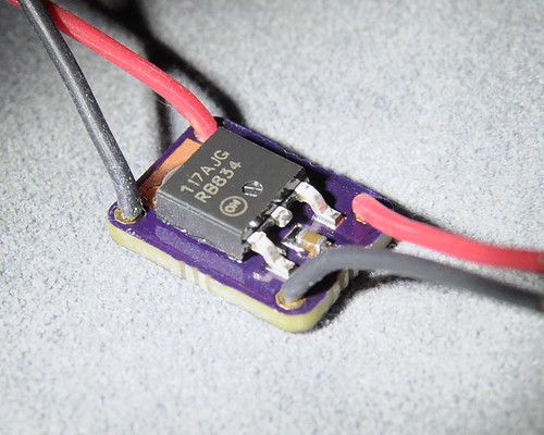
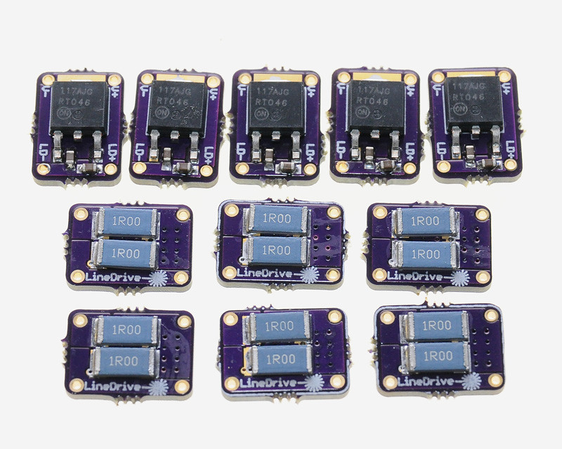
Having said that, I am semi-convinced that his driver uses an LM117 and NOT and LM1117 as specified - take a peak:
I'm just going by photos - I don't have one - but it looks like a 117 not a 1117 (two 1s versus three 1s)
Well they aren't the same IC

The LM1117 (what Jib lists)
- LDO Low Dropout
- 800mA current limit (that always confused me about his 1.3A drivers)
The LM117 (what the photos look like the drivers actually use)
- Not LDO Low Dropout (closer to 3.25V with resistor factored in - basically an LM317)
- 1.5A current limit (again, like an LM317)
MY THEORY
Here's what I think is going on. Jib is using an LM117 instead of LM1117. He's NOT using a low dropout IC. So even though his resistors are set to supply 2.5A of current, that will never happen because the DROPOUT voltage is preventing it. In other words, two cells give you ~8V, his circuit drops 3.25V. That leaves somewhere around 4.75V for the 445nm diode. Based on the 445's PIV curve, it is the VOLTAGE that stops the diode from sucking up 2.5A (and probably massive-over-current protection on the IC that would shut it down if that ever happened).
To test my theory, try using 3 cells with Jib's driver. USING A TEST LOAD! (don't kill a diode).
- I would be willing to bet that you see way more current than whatever you normally get with 2 cells. You may not get 2.5A since the IC will probably overheat, but I bet you'll far exceed what the current "limit" was thought to be.
My theory could be wrong - but that's what I'd put my money on.


