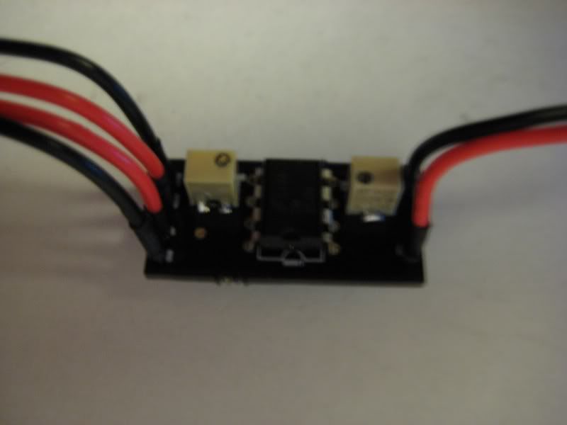
I actually built one of these about 2 months ago, but I failed. I gave up because I am waiting for summer break so I can figure out what went wrong.
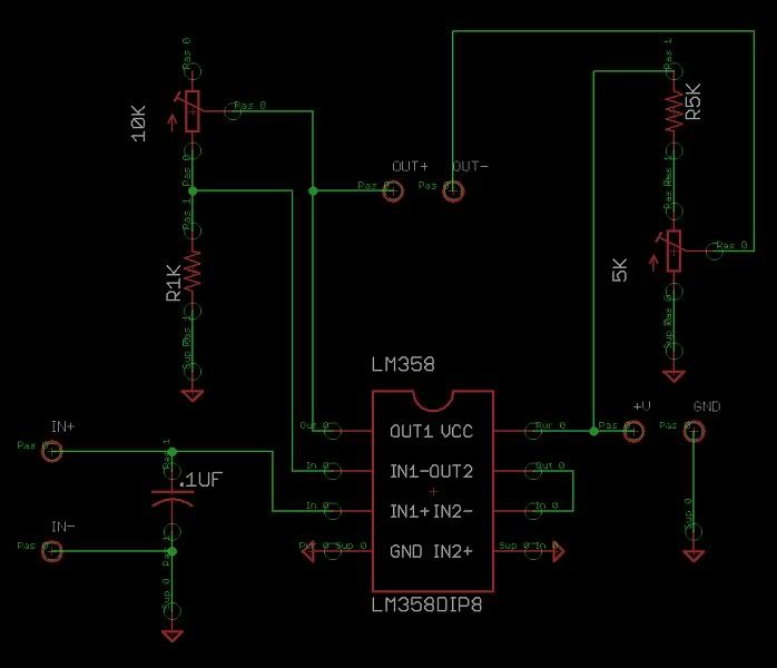
I used MarioMaster's and Jib's schematics but the readings seem to fluctuate a lot. It worked for a moment and I went eat dinner came back and it didn't work :undecided:
Schematic:
Well, yes, I turned the pots but I couldn't get it to zero. it would jump from 0 to 7V to negative 5V and back down and up and everywhere LOL. The board was extremely hot and I didn't know and burned myself
No, they are both bourns multiturn pots. Really expensive, about $4-$5 dollars for one trimmer pot.
Well, I didn't have one of those LCD voltmeters, so I used my DMM set to read volts. I kind of figured something was wrong when I noticed it got hot. Maybe something wrong with the schematic.
I messed with the pots so much I don't really know where they started. They just keep turning and turning never ending turning. :yabbem:
I haven't touched it since then. I keep it in a box next to my desk.
I'll be doing another try at this soon as finals are over. Order new boards and new parts and buy a LCD voltmeter.
Also make sure your orientation of your Lm358 is correct.. I can't tell which side of the PCB your view is of.. But if you mess up and get it flipped.. Your applying VCC to the out1... and that would certainly make it unhappy and probably get hot.
Your DMM should work fine though. All your doing is reading a voltage. Nothing special is required to do that.
Thanks! but I have extra LM358s but out of trimmer pots. I actually built 2 of these and both had the same problem.
I doubled checked every part to make sure they were oriented correctly, but somehow still didn't work out.
I just want to order new parts to start fresh on this again. I made a revision on my board, so hopefully it won't happen again.
EDIT:
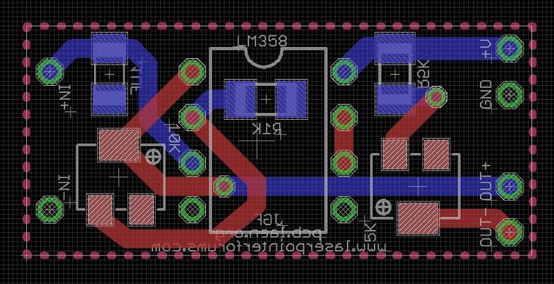
Sorry, red is top layer and blue is bottom layer. There are some connections you can't see because they are connected to ground and you have to run the ratsnest to see it.
Man your schematic and layout seem correct. Ive recently done a new layout of this circuit and it works great, if you want I can send you a spare board I have to test with:
Gah, I am envious of these little boards. Anyone want to produce me one that I will buy for ~$15-$20? I could build one myself, but I would make a messy job of it, and it would be huge in the end anyway (I would end up using through-hole components, probably, for ease).
Man your schematic and layout seem correct. Ive recently done a new layout of this circuit and it works great, if you want I can send you a spare board I have to test with: