HIMNL9
0
- Joined
- May 26, 2009
- Messages
- 5,318
- Points
- 0
Uh, i hope i have NOT contributed to start a war, with my posts, cause that was NOt my intention at all .....


Follow along with the video below to see how to install our site as a web app on your home screen.
Note: This feature may not be available in some browsers.


")

To answer your snotty questions as you posed them I'll
go through them as indicated by color above...

anyone got the circuit diagram for this project that was in post 1
its dissapeared now
thanks

")

dont worry sorted it
read through the whole thread and found that the meter need to be on a different battery to the amp that fixed the problem , spot on zero now
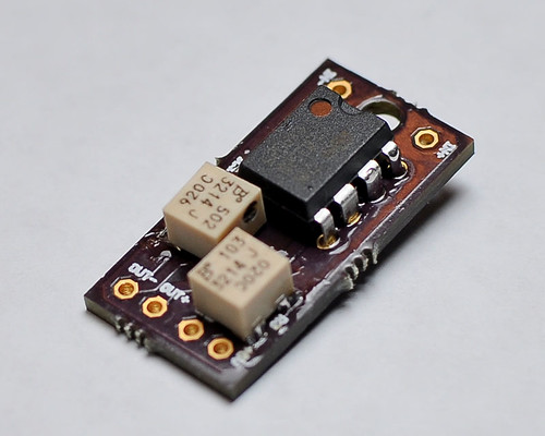
 ) ..... the only working solution is to use a little DC-DC converter for power up the head circuit, so the two grounds are galvanically insulated.
Great.
Post some Pictures if you can.
Some millivoltmeter modules don't allow the negative input pin connected to the ground pin of the power supply of the module itself, it's a limitation of the reading IC and cannot be worked around (and, trust me, i've tried almost anything, about it
would not using a diode on the ground fix the problem ??
or is that not worth me trying