Welcome to Laser Pointer Forums - discuss green laser pointers, blue laser pointers, and all types of lasers

Buy Site Supporter Role (remove some ads) | LPF Donations

Links below open in new window

FrozenGate by Avery

DIY Thermal LPM for under $50

^ no, i still use double power supply ..... i use DC-DC converters (actually they are cheap enough), cause the circuit take really few mA, and this way i can use also voltmeters that cannot have the GND in common with the power supply.


True, but if your using a DC-DC converter anyway, couldn't you still get the same result even using dual op-amp packages? I know it doesn't really matter. and 741's are ubercheap and common, but still.
 
I looked at the PCB artwork again and the trace coming
from the trimpot to the output seems to be awfully close
to pins 3 and 4 and also to pins 5 and 6 of the LM358...
Are you sure you don't have ant contact between those
pins and the trace... maybe through a small solder bridge.
You can check continuity or very low (0) resistance between
those pins and and the that trace to find any short...

Another thing.... are you using a ground plane on the
component side and the solder side or just the solder side
or just the component side. Difficult to see on the Artwork..
Do you have a pic of the top and bottom of an actual PCB..


Jerry

You can contact us at any time on our Website: J.BAUER Electronics
 
Last edited:
Here is the layers on my board updated:

Top:
attachment.php


Bottom:
attachment.php


I'm pretty sure the actual board there's no problem with my soldering. I'll post pics of the actual board tomorrow.. er I mean later today.

EDIT:
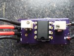
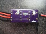
actual board pics!
 

Attachments

  • top.jpg
    top.jpg
    147.8 KB · Views: 715
  • bottom.jpg
    bottom.jpg
    151.2 KB · Views: 712
  • IMG_0166.JPG
    IMG_0166.JPG
    145 KB · Views: 261
  • IMG_0167.JPG
    IMG_0167.JPG
    149.3 KB · Views: 267
Last edited:
True, but if your using a DC-DC converter anyway, couldn't you still get the same result even using dual op-amp packages? I know it doesn't really matter. and 741's are ubercheap and common, but still.

Yes, but then you don't have any offser input pins, for use them as zeroing ..... let me some time for convert my "garbage schematics" (:p) in something readable, then i will post it, so you can see what i mean.
 
Here is the layers on my board updated:

Top:
attachment.php


Bottom:
attachment.php


I'm pretty sure the actual board there's no problem with my soldering. I'll post pics of the actual board tomorrow.. er I mean later today.

Those updated artworks are easier to see... I can see the
ground planes...
But I'm still worried about the red trace going between
pins 3 an 4 and the blue trace going between pins 5 and 6
of the IC...:thinking:

There is no great current going through those traces... just
make them thinner...(0.015" is just fine)..

Are these PCBs Solder Masked...????


Jerry

You can contact us at any time on our Website: J.BAUER Electronics
 
Last edited:
@ Jerry, he uses the same PCB service I use, so yes it is solder masked.
@ Jufran, Jerry is right, thick traces are not needed here like they are needed on drivers. the thickest trace on mine is 0.24".
 
Being Solder Masked that would reduce any
small solder bridges... That's why I asked...
Thanks...


Jerry

You can contact us at any time on our Website: J.BAUER Electronics
 
Last edited:
Sorry, I think I used a .4 trace, I like them big! :p

I'll make some corrections to the board (smaller traces, different components) before I send them off to be made.
 
Last edited:
Yes, but then you don't have any offser input pins, for use them as zeroing ..... let me some time for convert my "garbage schematics" (:p) in something readable, then i will post it, so you can see what i mean.

You can adjust the offset between the two stages similar to how it's done using a single op-amp for dual packaged op-amp's that don't have offset adjust pins.

It's a six of one, half a dozen of the other kind of thing. There are generally multiple ways to do most things, electrical circuit wise.
 
Last edited:
So I finally assembled my own LPM following this schematic.

Some questions though: is it a problem that it won't zero to 0? It will only go down to roughly .3mV.

Further, I am not sure which one is the calibration and which one is the zero.... Is 5k zero and 10k calibration? Not sure.

Further... I hate multiturn pots! They just keep on going! Why don't they stop, damnit?
 
Further... I hate multiturn pots! They just keep on going! Why don't they stop, damnit?

If you listen carefully you can hear a small click on every
rotation of most multi-turn trimpots when they are at the
ends of travel....

I love multi-turn pots....:eg:


Jerry

You can contact us at any time on our Website: J.BAUER Electronics
 
Last edited:
So I assembled mine....

I can't seem to get right on the calibration.... I think, anyway.

So I read about 137mV on my Rayfoss 200mW laser. That could be fine.

However, when I tested my blu-ray on it (12x running at 508mA), I was only reading about 480mV. I took off the lens and tried to get as much of the light onto the sensor and got around 560mV... so that means my calibration is most definitely off (people get 725+mW with a lens at 500mA, so without a lens I should be getting at least that, if not more).

So what's the problem? My pots is maxed out... calibration doesn't want to increase. Further, my 900mA 445nm laser is only running at like 450mV... so something MUST be off there, because it is definitely running at 900mA, and the diode isn't zombied....

So what's wrong?

EDIT: I replaced the pot with an 18k resistor (had it on hand) and the calibration seems better... EXCEPT, I am still getting higher numbers from my blu-ray than my 445. Is it possible that my blu-ray is stronger than my 445? Or is it possibly because more is absorbed of the blu-ray?
 
Last edited:


Back
Top