Welcome to Laser Pointer Forums - discuss green laser pointers, blue laser pointers, and all types of lasers

Buy Site Supporter Role (remove some ads) | LPF Donations

Links below open in new window

FrozenGate by Avery

CLOSED! Now Distributing ROUND 2!: THE "Skylaser" (laserBtB) groupbuy!

The Ophir head has two holes on each side. I think the case need heatsinking for more than 5 Watt lasers.

Its not like I have anything 5W+ but was thinking that it would be nice to have some sort of adapter plate so I could have a center hole for mounting on a tripod as well as having some heatsinking.


Extra NON-KEYED HL cap Offroad and keyed lp caps:p

My unshipped HL450 is emitting a high pitch wine....oh wait, that's me:crackup:

Still not understanding why the Ophir head if it is a 20C-A-1-Y is being called a 5W unit without extra heatsinking unless it is a different model number as it is listed in the spec sheet as 4W free standing.
http://www.ophiropt.com/blog/laser-measurement/heat-sinking-guidelines/ says that it is a 4W unit unless an extenal heatsink is attached to the outside screw holes provided.
No comments on how the power supplies are matched? Spec sheet says +-5V to +-18v regulated. From the pictures I've seen, how are you regulating your voltage? Anyone done the mismatched battery supplies test yet?
Thanks
 
Last edited:
After about 20 tries I finally managed to snap a picture of the misalignment.
attachment.php

Notice on the bottom it fades in a little, then is the actual output. On the top, while it's not too apparent in the picture, it's round :undecided:
 

Attachments

  • P2140345.JPG
    P2140345.JPG
    268 KB · Views: 177
No where all using the 20c. Check back a while ago I started a tread about the sensor that had some good info. I can't repost as I got in a bit of trouble with the person that original posted the info because I didn't site the source which I didn't know belonged to the guy as I found the picture on Google images and info on the forum.
 
If I could get a locking tailcap for my LP460 (free gift), that would be great. No big deal if not though.

Maybe I got lucky, but all of my lasers arrived and everything appears to be intact, no broken cases, no missing parts. I did get the correct gift, the blue LP460. But I can't LPM anything, so for all I know they could all be underspec. I guess the consolation there is that the diodes should be less likely to die on me.

Added you to te list we'l see if kev sends you one. It is a good thing you are happy with the purchase. When you get even more into lasers you will likely buy an LPM ;)

Extra NON-KEYED HL cap Offroad and keyed lp caps:p

Sawry :crackup: i corrected it :beer:

Didn't see those threads, I was reading the ones that turned up with a search of the keywords DIY, LPM, and Ophir. I had contacted the surplus bulk buyer of these 20C-A-1-Y heads before they started being sold on eBay. I bought 2 at $100 each and evaluated them for the buyer. I bought 100 more and advised the seller to sell the rest on eBay. The main reason I was looking at these threads was to see if they were being set up correctly. As Jerry advised, these are easy to damage by voltage imbalance between the + and - power supplies, and they are limited to a maximum of 18V as compared to the 24V limit of the 150C-A series. Voltage imbalance low enough to not damage will still affect the accuracy of the LPM reading. They really require fairly high precision balanced regulation of both + and - supply voltages if they are expected to meet the factory specifications they were calibrated to meet.

Bob

Hey there bob!

What would you say is the maximum difference in V the two 9V may be before the ophir is risking damage? You may want to check out my lpm thread in my signature. Jerry approved the setup as long as the batteries are in balance like you said. Also if you still happen to have any heads pm me :) And was the other member happen to be nospin?

greetings,
 
Last edited:
If we can get non-locking tailcaps for the HL hosts, I would be interested in that as well... preferably 3 of them, but whatever Kevin is willing to send, if any. I've noticed that the interrupt plug gets warm on a couple of the higher-power lasers, seems it is dissipating a bit of power.

Thanks again for running this GB, will be looking forward to the next! I hope the HL 635nm becomes available :)

Shame that the 473nm isn't available in the HL host :(
 
Last edited:
Those are some beautiful pics Brucemir:gj:

K, Ophir stuff.
I have little doubt that an Opher head can handle some pretty good W's for a short period of time. No idea what this would amount to.
Looking back thru other posts what I saw was that the units were called 5W once a display was found to read that high. The units are rated for 4W. This may sound picky to some. From what I've been able to piece together, the voltage supplied to the head along with the heatsinking is what determines the potential reading. However, just because my speedometer says 160mph doesn't mean the car can go that fast;) If I use my Fluke 87V, I could call it a 20W even though it has no additional heatsinking (range is .01mv to 1000V DC with a .03% to .1% accuracy depending upon range). In comparison, my least expensive Fluke (model 110) resolution is 1mv to 6V at .7% to 1% accuracy.
Can't seem to find any real world testing or data concerning what kind of duty cycle the unit can handle. Are the ratings for continuous power? If they are, you could certainly test alot higher than 5W without any issues for a short duration.
Ran a quick test with (2) 9volt cells reading 9.77/9.76V. Had a slightly fluctuating 3.7-4.1mv reading no load. Tested a very steady unit at 65.1mw for 5 seconds. Tested again changing one cell out with a an 8.42V cell and read 4.1-4.4mv no load and got a slightly higher 68.2 reading. So with a 1.34V inbalance the reading changed 5%.
Readings were taken quickly with 1 minute cooldown on laser. Testing is subjective. Only ran the test once.
No plans to test with a bigger imbalance as I'm not interested in potentially frying an ophir. Took a chance to begin with so I could have more to say than just posing questions for others to answer.
You need to be careful about reading too much into the quick test as variables can change quickly. Dealing with batteries in the laser and ophir. The Fluke 87V is quite accurate. Doubt the displays members are using have .03% accuracy up to 500mv. Nothing was moved during the testing.
Again, this information is for all of us. Would encourage comments/discussion on all of this. I'm just posting what I believe to be accurate information but I could be incorrect about things. Anyone with more information (especially anything published by the manufaturer) is MOST welcome. I'm a technician by trade and despise geussing.
I only have one Variable DC regulated power supply (same one as Blord:wave:) so I don't have 3 decently stable power supplies (2 for ophir and one for laser) although I could certainly "rig" something up. Not worth it to me at this time.
Haven't decided yet on actual mounting or anything for the ophir pieces/parts. Have an older original Fluke 87 that I changed the backlighting in from green to white leds and it's possible I may just use it (.1mv +- .1%). Got it brand new sealed in box at a yard sale that our entire neighborhood does once a year a couple years ago fro $10:D:takeit: I believe the lady who was selling it lost her husband or something and was just getting rid of some things. Snatched it up immediately and didn't ask for a lower price:crackup: Cost me almost 3x as much to purchase a white led background display:yh: The 87 version 3s initially came with a green background but at some point it was changed to the white.
Don't want to run double 9v in series on each + - because a new cell is closer to 9.7v and lithiums are almost 10v. It was mentioned to me that + - 12v should be good for about 10Watts.

Not sure back when Jerry posted about the 20C head why he said it can go to 5W max with heatsinking. There's a note (a) reference under Maximum power that says "With analog "A" version, maximum power is also limited by maximum output voltage where output voltage is at most 2V less than input voltage"
I was informed (not by Jerry) that the maximum reading is limited to supplyu voltage -< 2 vdc, so if you power it from +/- 12 vdc it'll top out at about 10W (10 vdc analog output). Believe that this should mean that at 18v max input voltage you would actually get a max of 16W or 16V DC on analog output. So, this would mean that the actual max output for the 20C head is 16W . Again, could be wrong but this is how I'm interpreting it. If you only supplied the minimum 5v to the head what would you be able to read to? Looks like 3W.
 
Last edited:
I finally got the Laserbee II meter and have some GB results to post for what they're worth.:pop:
I obtained some AW IMR16340 550mAh batteries and an Ultrafire WF-138 charger. I placed the freshly charged batteries in the laser(s) and took the measurements (I could not graph the
results because of some glitch in the computer/interface :confused: that I haven't dealt with yet).

DPL 460nm 100mW rated - 86mW peak actual :undecided:
DPL 405nm 500mW rated - 597mW peak actual :eek::yh::yh::yh::beer:

I don't have batteries charged yet for the 632nm 120mW rated pen (with some "used" alkalines it peaks at 81mW).

T.
 
Last edited:
Tes, not surprised at the overspec 405. Can't remember ever getting a 405 from anythwere that wasn't overspec.
The 450 reading is one of those annoying "what do I do now" things. Think I would take multiple readings on it. Do you have a multimeter so you can check the voltage of the IMRs just to make sure they are at peak? Annoying to be just under spec:(

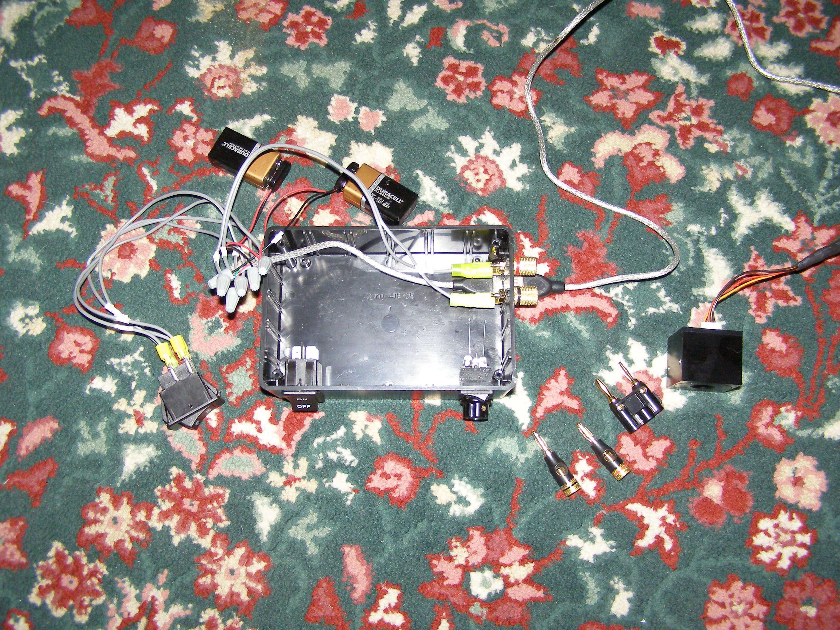
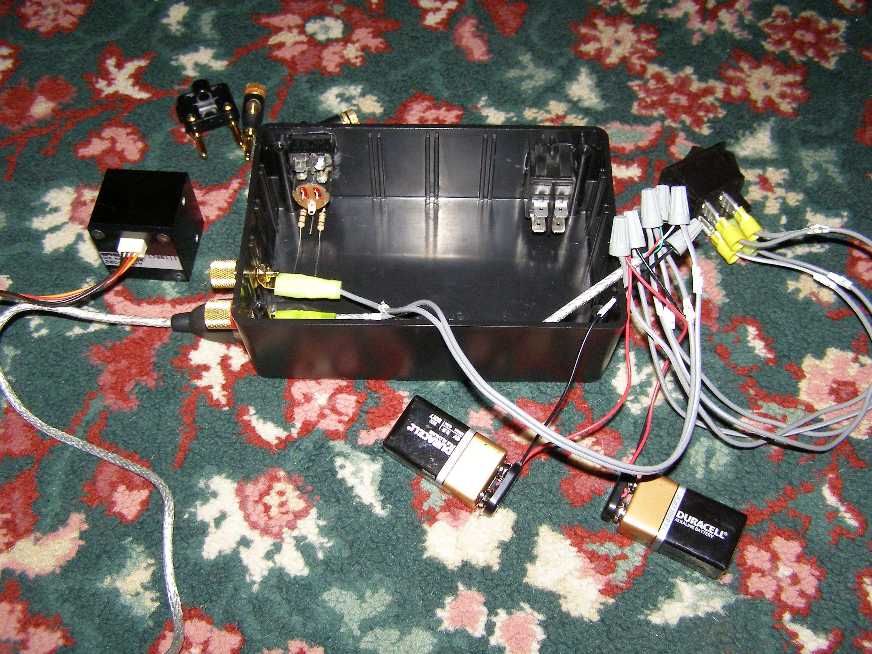
What I've thrown together so far as a mock up so far.
It appears that Awillis and I likely bought the same pack of USB cables. I think I got them at BJs club a few years ago. Easy to add another length if you need too. Found his idea about using the USB cables intriguing (he gets full credit);):wave:
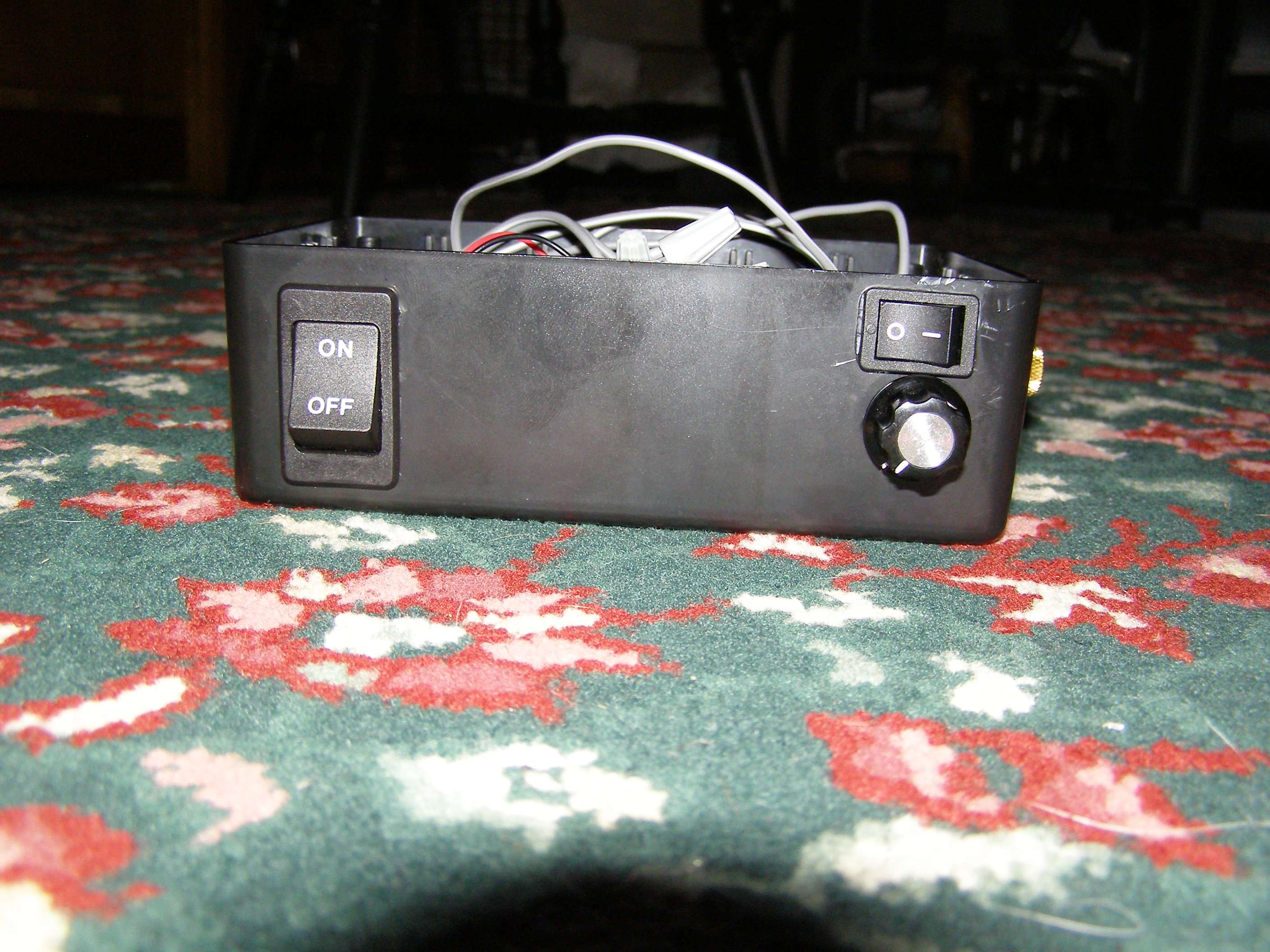
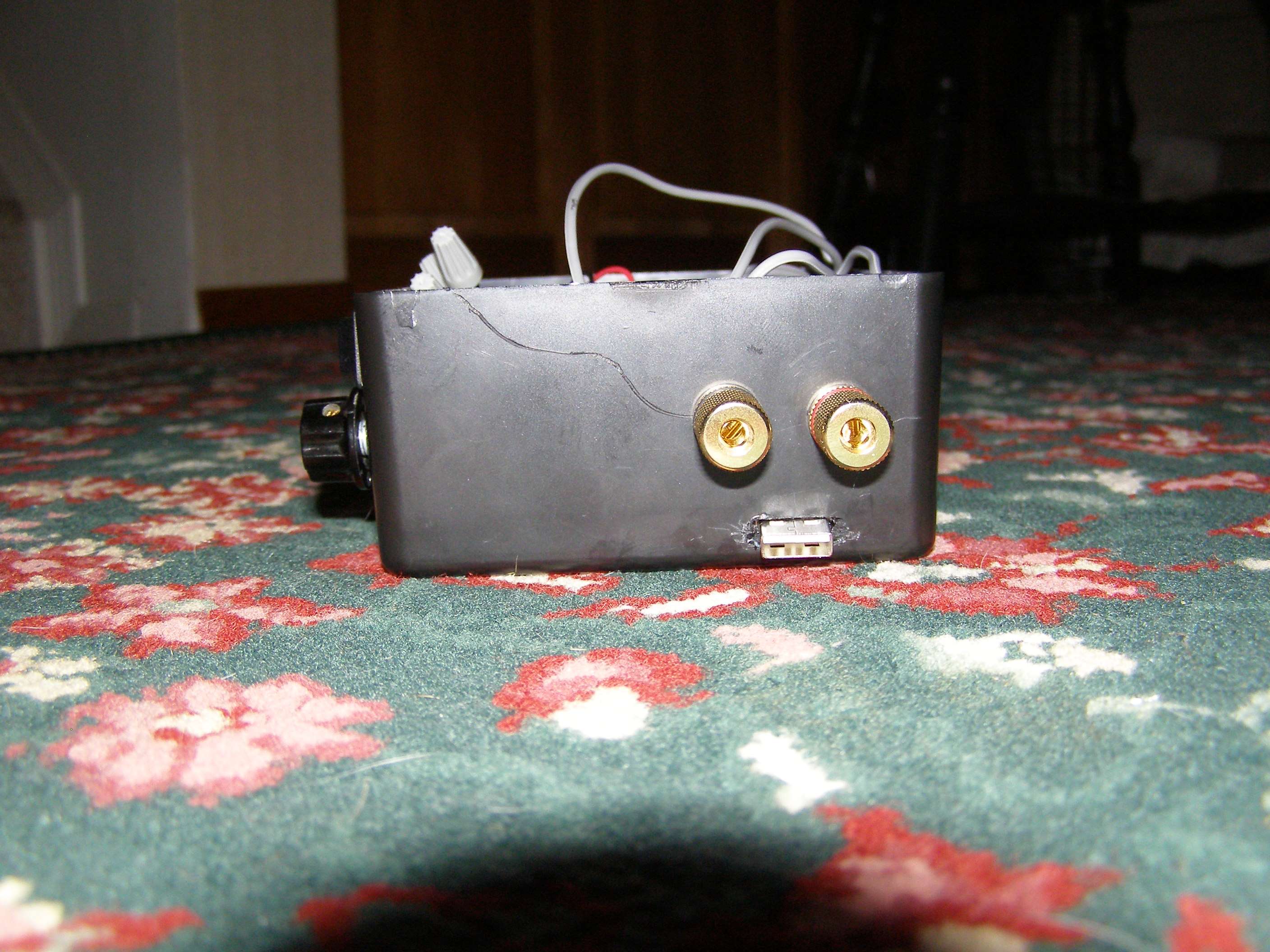
Obviously the wiring is just a temp throw together to check things. You can see the main dpst switch in the box is the same as the loose one. Didn't hook that switch up just to make things easier to work on for now since I can pull out the whole wiring harness. The right switch (spst) and 10k pot with 100k resistors are there for switching on a 5V display panel and having a zero adjust when he used a switching power supplyto provide +/- 12 vdc plus +s vdc to power the display (this info. was from Bob_Boyce). Just installed these things so I have options to try out. The extra connectors above the usb is for direct multimeter reading so you don't have to use the display (really like this option and if your meter has a REL function you allready have a zero adjust built into the DVM). These connectors are banana plug compatible and are spaced properly. This is a simple project box from radio shack that I had (#270-1806). It is 2" x 6" x 4" which makes wiring and parts placement a bit easier than some of the smaller boxes.
Have some 9v battery clips that I could use to hold them but the batteries would have to be on their side as they lift the 9v just high enough with the heavier duty battery connectors to keep the top from closing. Could get the cheaper ones though and likely stand them upright or gasket the top to raise it up slightly.
Decided to put all the swiches/adjustments on the front so I'm not second geussing myself on switch positions.
Technically I could rob parts from my other LPM to put the rest together:p Keeping the other one though so I haven't decided. Got some time on my hands to tinker this weekend and it's getting hard to hold myself back:crackup:
This box/setup may be changed at anytime or I might keep it this way for quite awhile. Not the greatest job but as I said, this was thrown together rather quickly.:beer: (although I don't drink:whistle:)

p1010043uj.jpg

p1010042wm.jpg

p1010041m.jpg

p1010044p.jpg

p1010045wb.jpg

p1010046qd.jpg
 
Last edited:
@Marcopolo the 473nm module is probably wider than the HL itself

I'm also waiting for the next GB, I could still use a SM 635.
 
My friend Bob and I worked out something (see page 50) as he felt sorry for my frustration trying to help others out with accurate measurements:p
You did a good job calibrating the lpm you made for me:thanks:. It really is quite accurate :yh:
Have been trying to go thru all the builds to see what you all did. Where did you get the 9v to 5v converter and the 5V panel from? Would really apreciate it. Seen any straight 9V ones? Think Offroad has one....
Anyone can easily add the connections for a mltimeter. Obviously I'm just jumpering off the signal wires.
Got to the point of messing with the build/box that I don't have any other parts to go on unless I purchase the same 5V panel that's in the lpm you made me so I could cut the hole or decided to build the +/- 12 VDC external power suply. I've got a couple power blocks that output 12V and 5V at 2Amps. They are from a couple SATA/IDE to USB 2.0 adapters.


Back
Top