daguin
0
- Joined
- Mar 29, 2008
- Messages
- 15,989
- Points
- 113
I have had several inquiries about this. I thought that I would place this info in a bit more focused way. This thread focuses on the Wicked Lasers Spyder III Arctic because people with Arctics are who ask most often. However, the info about the diode and beam/spot, in the first part of this post, pertains to ALL lasers made with this 445nm diode.
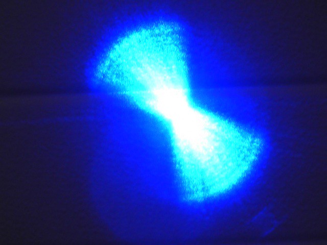
Before you do anything, make sure that your laser actually has a problem. The diode used in these is multi-mode. It does NOT produce a "spot." It produces several "lines." The higher the mW, the more "lines" produced. The colimator makes the line a bit more of a rectangle, but it is not and will never be (without significant external optics) a round dot. This is what the raw diode output looks like:

Here is link to a great video of what the raw output of the diode looks like at different currents.
Thank you, anselm
http://laserpointerforums.com/f48/video-raw-output-blue-nichia-diode-60488.html
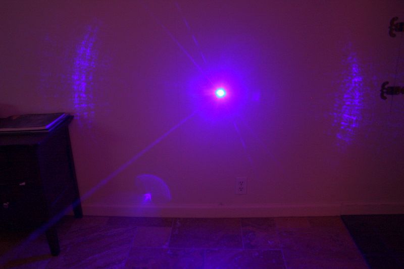
This is what a well colimated "spot" looks like at about 40 feet.

With a higher output lens it is even more elongated. Here is one with a high output lens at the same distance

This is one of the many lies that laser sellers tell about these diodes. They are NOT TEM00! If your "spot" is anywhere close to these, it is as good as it gets. Don't mess with it! You will be taking the chance on breaking your laser for nothing
Also, the higher output lenses may also show a "phantom square" (or other "noise") above the "spot." This is normal. There is always some spurious emission around the edge of the die. Your lens is just picking that up and focusing it along with the main beam. With this diode, sometimes you must adjust your expectations from this diode (or get a lower output lens") ) instead of trying to adjust the output.
) instead of trying to adjust the output.
Finally, the width of the emission often reflects off of the sides of the lens nut. The result of this is a "spray" of light from two opposing sides of the beam
If yours is significantly more elongated than the pictures above, then WL did not adjust it (or maybe assmble it) correctly. Now you have to decide if it is worth taking the chance on breaking it.
The next part deals specifically with the Arctic
There are several "variations" in the Arctic. They are "basically' the same in this area, but there is some variability. This is the basic design.
When you remove the outer "lens" you should see something like this

This is the diode/collimator/aperture assembly
If you removed the whole assembly, it would look something like this

You DO NOT want to remove the entire assembly. This is just to get you to recognize which parts you are going to be working with.
Here is the assembly completely removed

You should be able to see the aperture and the diode holder in this picture. The aperture should unscrew from the diode holder.
Here is the aperture removed

Here you can see the colimating lens which is under the aperture and inside the diode holder.
You have to hold the diode holder in place while unscrewing the aperture. If the diode holder spins, you take a chance of breaking the wires that are attached to the diode or breaking off the diode pins.
If you are successful at removing the aperture, then you have access to the collimator. You can then use a screwdriver (or other tool) to adjust the collimating lens.
In some of the Arctics, the collimator is glued in place. In some of them the aperture is glued in place. If yours is glued in place, you are pretty much screwed. If you can move it, then you can adjust it and then reassemble it. If not, then adjust your expectations and/or attempt an RMA (good luck )
Peace,
dave
Before you do anything, make sure that your laser actually has a problem. The diode used in these is multi-mode. It does NOT produce a "spot." It produces several "lines." The higher the mW, the more "lines" produced. The colimator makes the line a bit more of a rectangle, but it is not and will never be (without significant external optics) a round dot. This is what the raw diode output looks like:
Here is link to a great video of what the raw output of the diode looks like at different currents.
Thank you, anselm
http://laserpointerforums.com/f48/video-raw-output-blue-nichia-diode-60488.html
This is what a well colimated "spot" looks like at about 40 feet.
With a higher output lens it is even more elongated. Here is one with a high output lens at the same distance
This is one of the many lies that laser sellers tell about these diodes. They are NOT TEM00! If your "spot" is anywhere close to these, it is as good as it gets. Don't mess with it! You will be taking the chance on breaking your laser for nothing
Also, the higher output lenses may also show a "phantom square" (or other "noise") above the "spot." This is normal. There is always some spurious emission around the edge of the die. Your lens is just picking that up and focusing it along with the main beam. With this diode, sometimes you must adjust your expectations from this diode (or get a lower output lens
) instead of trying to adjust the output. Finally, the width of the emission often reflects off of the sides of the lens nut. The result of this is a "spray" of light from two opposing sides of the beam
If yours is significantly more elongated than the pictures above, then WL did not adjust it (or maybe assmble it) correctly. Now you have to decide if it is worth taking the chance on breaking it.
The next part deals specifically with the Arctic
There are several "variations" in the Arctic. They are "basically' the same in this area, but there is some variability. This is the basic design.
When you remove the outer "lens" you should see something like this
This is the diode/collimator/aperture assembly
If you removed the whole assembly, it would look something like this
You DO NOT want to remove the entire assembly. This is just to get you to recognize which parts you are going to be working with.
Here is the assembly completely removed
You should be able to see the aperture and the diode holder in this picture. The aperture should unscrew from the diode holder.
Here is the aperture removed
Here you can see the colimating lens which is under the aperture and inside the diode holder.
You have to hold the diode holder in place while unscrewing the aperture. If the diode holder spins, you take a chance of breaking the wires that are attached to the diode or breaking off the diode pins.
If you are successful at removing the aperture, then you have access to the collimator. You can then use a screwdriver (or other tool) to adjust the collimating lens.
In some of the Arctics, the collimator is glued in place. In some of them the aperture is glued in place. If yours is glued in place, you are pretty much screwed. If you can move it, then you can adjust it and then reassemble it. If not, then adjust your expectations and/or attempt an RMA (good luck
)Peace,
dave
Last edited:


 Well this is embarrassing.