Welcome to Laser Pointer Forums - discuss green laser pointers, blue laser pointers, and all types of lasers

LPF Donation via Stripe | LPF Donation - Other Methods

Links below open in new window

ArcticMyst Security by Avery

Blue laser 74W NUBM35 Portabl?

Joined
Jul 10, 2015
Messages
9,890
Points
113
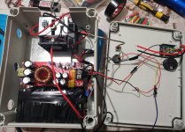
If you want to use a linear like that configure it as a current regulator not a voltage regulator, also you need DC not AC


Borislav@87

Active member
Joined
Mar 20, 2022
Messages
355
Points
43
So how do I make it only regulate current and not voltage? In this case, both will be regulated, or at least that's what I think. I can't find DC. Only this Ac 50-220V
 
Joined
Jul 10, 2015
Messages
9,890
Points
113
If you want to run it off your mains AC you need to convert to DC via transformer, bridge rectifier and then configure a linear such as lm338 as a current limiter, we have already been over this about how to use a lm338 as a current limiter, just read back or just buy a power supply.

edit:
You likely want a switching power supply then use your dc to dc current limiter or a mini power supply, just type what you want into ebay, amazon, ali express
 
Last edited:

Borislav@87

Active member
Joined
Mar 20, 2022
Messages
355
Points
43
My question was different. I will use batteries. My question was if I could put something like a potentiometer and adjust the power of the laser easily and conveniently by turning. I will not use AC power. The potentiometer should be put after the driver output + and - so that I can limit the power of the laser and increase it
 

Borislav@87

Active member
Joined
Mar 20, 2022
Messages
355
Points
43
Yesterday I made the battery power supply with 18pcs 18650 24V batteries. I will also get the laser array one of these days. It is now in my country
 

Attachments

  • Screenshot_20230125_084429.jpg
    Screenshot_20230125_084429.jpg
    895.8 KB · Views: 8
  • Screenshot_20230125_084529.jpg
    Screenshot_20230125_084529.jpg
    965 KB · Views: 8
  • Screenshot_20230125_084725.jpg
    Screenshot_20230125_084725.jpg
    980.4 KB · Views: 7
Joined
Jul 10, 2015
Messages
9,890
Points
113
Very nice but let me offer a suggestion, when soldering thicker wire to batteries use a 100-150W soldering gun or large soldering iron so you can liquefy all the solder at once and make a good uniform connection, because using too small of a soldering iron the larger material sucks the heat out and you can get a cold solder joint....... or you can hold your soldering iron in one spot to press everything together to preheat the material and then slowly add solder keeping the pool liquid, but a bigger gun/iron makes it easier and you don't have to heat everything as long.


WizardG

0
LPF Site Supporter
Joined
May 9, 2011
Messages
1,188
Points
113
Very nice but let me offer a suggestion, when soldering thicker wire to batteries use a 100-150W soldering gun or large soldering iron so you can liquefy all the solder at once and make a good uniform connection, because using too small of a soldering iron the larger material sucks the heat out and you can get a cold solder joint....... or you can hold your soldering iron in one spot to press everything together to preheat the material and then slowly add solder keeping the pool liquid, but a bigger gun/iron makes it easier and you don't have to heat everything as long.

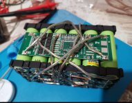
Seconded: you need more heat. Soldering directly to the batteries is a bit tricky. You want to minimize the amount of heat, especially when soldering to the positive terminal. Using a higher power iron or gun will allow you to make good solder joints in just a few seconds rather than slowly 'cooking' the battery trying to melt the solder with a lower power iron. The risk with the high power gun is there's no temperature control so you must work quickly to avoid melting the seal around the positive terminal.
 

Borislav@87

Active member
Joined
Mar 20, 2022
Messages
355
Points
43
Everything is already done. I'm waiting a few days to get my laser array. It turned out very well. The voltmeter shows the battery level and the other voltmeter and ammeter will show the consumption of the array. The fans run on 15V
 

Attachments

  • Screenshot_20230126_003114.jpg
    Screenshot_20230126_003114.jpg
    978.9 KB · Views: 10
  • Screenshot_20230126_003102.jpg
    Screenshot_20230126_003102.jpg
    956.1 KB · Views: 10

Borislav@87

Active member
Joined
Mar 20, 2022
Messages
355
Points
43
I share my experience with the BMS that I used for the pack of 18 batteries. I know how to connect B-, B1, B2, B3, B4, B5 and finally B+. 3 out of 4 BMS proved to be defective. I put the big ones on first. The first one didn't work at all. I took it off and put the second one on. Everything worked for exactly 2 days. After the second day without use, it broke down on its own. Just refuse to work. There was no current at the outlet. Then I put these on top of the little ones. I had 2 of them. The first one didn't work at all. I put the other one in and it works fine so far. I had information from an acquaintance that these BMS have many defects, because according to him, out of 100 bought, 40 were defective
 

Attachments

  • 4542086171080245559.jpg
    4542086171080245559.jpg
    253.1 KB · Views: 3
  • -561971884-979730745 (1).jpg
    -561971884-979730745 (1).jpg
    219.4 KB · Views: 3
Joined
Jul 10, 2015
Messages
9,890
Points
113
This could well be an issue with intermittent connections, you could use one of those spot welder circuits to make your battery connections.

Also was thinking we could knife edge the two rows of 7 beams from each NUBM35 so the cluster of bars overlap at the max useful distance.

SANY6866.JPG
 
Last edited:

Borislav@87

Active member
Joined
Mar 20, 2022
Messages
355
Points
43
This could well be in issue with intermittent connections, you could use one of those spot welder circuits to make your battery connections.
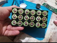
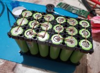
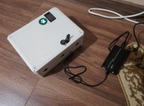
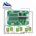
It's not their problem. I checked everything. Everything is soldered very firmly. All connections had the corresponding current B1 B2 B3 B4 B5 B- B+ coming. There was no electricity at the exit itself. With the other BMS, there was no voltage in B3. It was showing 2V. I thought so too, but it's not their problem. Also when I measured the ends of the batteries it showed 24.8V. There was no current at the output of the BMS
 
Joined
Jul 10, 2015
Messages
9,890
Points
113
You can get a voltage reading and still have a cold solder joint fail under load, bad solder joints can be intermittent......now that may not be the case in your case, but then again it just might be, if you continue to have issues you may want to rule it out by re-connecting your batteries.

Also if you have a 2nd battery pack you could do some diagnostics by proving a board good on a 2nd battery pack, then see if it works on your 1st pack......If for instance you were planning to build a 2nd pack anyway maybe use the spot welder to make your connections, or a bigger soldering iron.
 
Last edited:

Borislav@87

Active member
Joined
Mar 20, 2022
Messages
355
Points
43
Both BMS were damaged as soon as I put them in, probably a factory defect. There was no load. The other one was working and without me using anything it stopped working by itself. I also resoldered a few solder joints just in case but to no avail. In my opinion, problems are only from bms.


Top