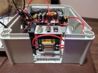
Farbe I haven't scoped these drivers yet, but they do have caps on board and I haven't had any trouble with mine yet, yes I know that's not a proper test and is no guarantee, that said techhood in China has sent me defective stuff before and I test my laser diodes and arrays with a quality bench top power supply when they 1st come in, so I know of the 2 nubm35 arrays I bought from techhood that one had a dead diode and a weak row when I got it, the other is just fine and has held up well.
---------
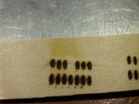
Boris I can see a gap under your array and that's a gob of compound, you only need to use a small amount spread out in a thin layer and you need to make firm contact with your heat sink.
p.s. Don't test the array without a heat sink when you 1st get it, there is very little material to absorb a lot of waste heat.