Welcome to Laser Pointer Forums - discuss green laser pointers, blue laser pointers, and all types of lasers

Buy Site Supporter Role (remove some ads) | LPF Donations

Links below open in new window

FrozenGate by Avery

Blue laser 74W NUBM35 Portabl?

I will do that too, just in case he does not read the direct message.
Thank you once again for your time, and apologize for the initial controversy.
No prob man. I can be too "direct" at times


@RedCowboy
I powered this driver with a 12V 3A adapter and the voltage it output is 68V. 8 volts more than it says.

I also checked for initial current spikes with this 100W ice. I couldn't see any
 

Attachments

  • Screenshot_20221223_211112_edit_1125890471286529.jpg
    Screenshot_20221223_211112_edit_1125890471286529.jpg
    586.7 KB · Views: 7
You won't see spikes with a multi meter, you would need to use an oscilloscope to capture a trace.
That said today's mm blue ld's are pretty robust.

 
In the case that this driver can do 68V output power, I guess it would be able to power all 14 diodes together connected in series. In this case, 6 pcs 18650 batteries should be enough for power supply. I'm asking because there isn't much space in the box and if one driver would do the trick, I'd try just one driver and 6 batteries to start with.
 
@RedCowboy
I received the laser array today. I decided to check if everything was ok. Since I didn't have the ability to adjust its amperage, I initially set 25V to one row of diodes and then increased it to 30v. Then I also raised the amperage, but I didn't know how much. It definitely started to glow very brightly. I tried it and it lit cardboard instantly. But again I say this is just a test to know that everything is ok. Without cooldown, I didn't risk a long glow. I decided to just use one driver connected to 24V with 12 18650 batteries. This driver can output up to 67V, not 60V as it says, so it will work. As a last resort, I have a more powerful one (1800W) But I don't believe this one will fail. Definitely though with half the dido I really liked the power of it and the color of the blue. It's like NUBM0E. Still waiting for 20pcs batteries to arrive. The ones I'm using are old, but I'll play with them for a start until the new ones arrive.
 

Attachments

  • Screenshot_20230106_180340.jpg
    Screenshot_20230106_180340.jpg
    632.6 KB · Views: 11
  • Screenshot_20230106_180301_com.huawei.himovie.overseas_edit_1596431263648580.jpg
    Screenshot_20230106_180301_com.huawei.himovie.overseas_edit_1596431263648580.jpg
    952.6 KB · Views: 11
You don't want to power that array without it being thermally bonded to a heat sink, even a chunk of aluminum will do, but don't run it naked because it will damage it quickly.

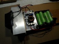
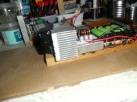
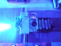
I bought some of those drivers and they do work, here's a temporary test rig I threw together, at 3.0A to the 1 row of 7 diodes the driver is sucking down 7A from the 4 batteries, this was when the batteries were charged @ 4.2v each but now that they have discharged to 4.0v each the driver is putting out 2.5A to the string of 7 diodes and the 4 cells sag from 15.9v to 14.3v under load, maybe the pot had just settled in, but I think I will try 6 cells and see how constant my setting of 3-4A stays put as they discharge.

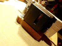
I also made an expedient lens flare hider that I can also glue a concave lens to and then focus with a sliding convex lens, yes I know that I need to mount a small fan at the end of the heat sink, I've been using a portable fan because this is a very temporary test bed and in no way a finished unit which would be much more compact if I were to use these arrays, what I would do is knife edge many of the 7 diode strings, this will improve the performance quite a lot, but I think the NUBB14 arrays would be better as the footprint should be tighter, really should build my own array from c-lens corrected 44/47 diodes, but again there is a better way and this is just for fun, still the current output needs to stay put at the fully charged setting, I will do some more testing later and compare the efficiency of these switching drivers against the linear when powering multiple diodes, it may not be all that far apart in reality.

SANY6762.JPG
SANY6768.JPG
SANY6764.JPG
SANY6761.JPG
SANY6767.JPG
 
Yes, these drivers work stable. I used 6 pcs 24V batteries with BMS for the test. But I haven't tested anything because there was no cooling. These days I will do tests, but only with 6 batteries at 24V. With 12 batteries, the work will be more stable. This has already happened with the glare. I will share these days results
 

Attachments

  • Screenshot_20230106_200135_edit_1602337137929971.jpg
    Screenshot_20230106_200135_edit_1602337137929971.jpg
    928.7 KB · Views: 2
That will be the cooling. I also put a thermal switch at 70C to turn it off.
I saw that your array was stacked vertically, I put it horizontally. It will probably make the beam look wider, but that's not a problem for me.
 

Attachments

  • Screenshot_20230107_122940.jpg
    Screenshot_20230107_122940.jpg
    753.6 KB · Views: 5
Today I did a test with all 14 diodes. The driver handles fine, however the BMS battery protection kicks in when it picks up more than 3.5A and breaks the circuit to the driver. Two of them are different and were not loaded. They also warmed up. Without getting the new ones I won't be able to set up the driver. Because it won't work with these batteries. I have to wait. Also, 12 batteries will work much more stably than 6 pcs.

Edit: In fact, I am waiting for 20 batteries and I will make a 24V power supply with 18 batteries. I don't need them anyway. So everything will work very stable.
 
Last edited:
That will be the cooling. I also put a thermal switch at 70C to turn it off.
I saw that your array was stacked vertically, I put it horizontally. It will probably make the beam look wider, but that's not a problem for me.

Don't run it like that, that will definitely cook the array in record time. Thermal paste (i suspect that's what you used, not thermal glue) is just there to fill the microscopic spaces between two flat metal blocks, it's not to be used as a mm thick layer. You apply a small amount (for that area a blob half the size of a pea should do) and then you screw the diode to the heatsink TIGHTLY.

NEVER run it the way you did, the thermal conductivity of thermal paste is shit-> your current setup is just barely better than no cooling at all.
Remove the thermal paste, figure out where to drill holes in the heatsink to mount that array, then clean both surfaces with isopropanol, apply a small amount of thermal paste (spread it across the array) and screw the array to the heatsink.
 
Yes, but I will do it with the other lazar array. This one broke down. Even when I took it off all four pole pins had play. Yesterday, during the first test, it broke once, but I thought it was from a loose contact. Today I made a bridge between the two lines and 3 hours ago I tried to set up the driver. I turn everything on and surprise, it doesn't work. I wiggled the pole pins slightly and it went for a bit and stopped again. After that it stopped working. It's not my fault because I was very careful with these pins, especially when I saw them move early on. And yet they broke down. The laser array works, but the pole pins do not make contact. I don't know if there is a way to repair this, but from what I can see there isn't. I placed a new order for a laser array

 
That's toast, my guess is that you broke the bonding wire. To fix it you'd have to open it, and without a cleanroom that operation is also going to kill it due to dust.

Best practice is to use some sort of strain relief as well as silicone cables (the flexible ones): You fix the cable to the heatsink (with a cable clamp or something else, get creative) so that you have a short (few cm) piece of cable at one side of the clamp that you solder to the array and a long piece at the other side to connect it to the driver. That way, even if you yank at the cable going to the heatsink you're only pulling on your strain relief and not on the diode pin.
Also, spend the extra few bucks for silicone cables: You are currently using stiff cables with PVC insulation, if you use cables with flexible silicone insulation you have an easier time stuffing the cable into the housing and if you bump the cable it'll just flex instead of transmitting that force to the pin of the array.
I had taped all the wires to the radiator so there would be no movement. The problem with the pole pins has been there ever since I took it off the board. The next one I won't take it off, I'll cut the circuit board and it will stand for it. I will solder the wires directly onto the board's poles. I would try to open the laser array but I don't know how. I guess I have to take the lens off first. When I look at it, it is glued. It won't get any worse in this case. So I would appreciate if someone could advise how to open the array
 
I removed the lens. I can see all four pins. All move freely. I don't know what to do from here. I probably need to cut it with something to get to the crystals and poles
 

Attachments

  • Screenshot_20230108_003515_com.android.gallery3d_edit_1640738845472548.jpg
    Screenshot_20230108_003515_com.android.gallery3d_edit_1640738845472548.jpg
    980.1 KB · Views: 13
  • Screenshot_20230108_003529_com.android.gallery3d_edit_1640730344779321.jpg
    Screenshot_20230108_003529_com.android.gallery3d_edit_1640730344779321.jpg
    455.5 KB · Views: 13
  • Screenshot_20230108_003535_com.android.gallery3d_edit_1640720635224635.jpg
    Screenshot_20230108_003535_com.android.gallery3d_edit_1640720635224635.jpg
    268.8 KB · Views: 13
I opened it. Everything is broken. I don't know if I will be able to connect the poles. It's very subtle work.
This is impossible to fix. I can only try to connect the pins to the home board but I see that each pole has 3 wires
 

Attachments

  • Screenshot_20230108_010456_edit_1641191435106854.jpg
    Screenshot_20230108_010456_edit_1641191435106854.jpg
    493.5 KB · Views: 13
Last edited:
Now it's 100% dead. You would need a wire bonder to reattach the wires to the pin (it's just 3 wires to account for the high current), and a single dust particle on the actual laser diode will kill it as soon as you turn the laser on. That's why i said that you would need a cleanroom, if you just open it in a normal room (and touch it with bare hands) that's an instant death sentence for the diode.

Tip for the next array: DO NOT rotate the pins at all


Back
Top