upaa27
0
- Joined
- Jul 10, 2013
- Messages
- 617
- Points
- 28


Follow along with the video below to see how to install our site as a web app on your home screen.
Note: This feature may not be available in some browsers.


 I am happy to report the coil came right to life.


I did try that, it didn't do much though. The 7414 has too wide a hysteresis band(it did work for some people though) so the newer drivers use a comparator. Hmm... :thinking:
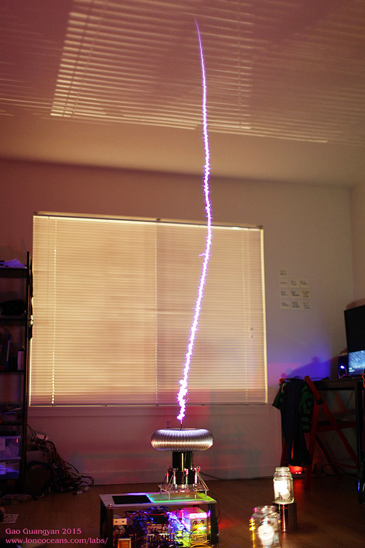
It's something else to be able to create a virtually straight "bolt" , without streamers , any videos?
Regards
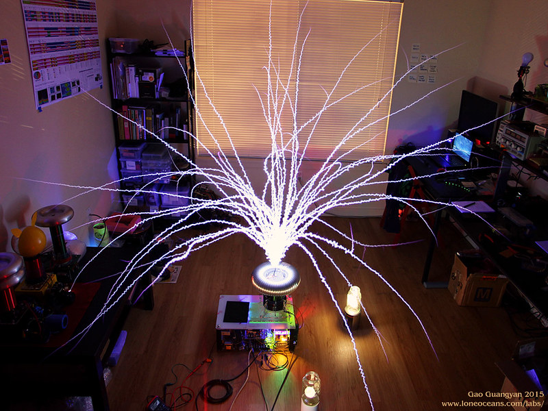
") Creating a single 'bolt' with no branching is essentially the main goal when developing this type of Tesla Coil. It was a bit of work to get right but it seemed to eventually work out. It's somewhat mesmerizing to see in real life.
Creating a single 'bolt' with no branching is essentially the main goal when developing this type of Tesla Coil. It was a bit of work to get right but it seemed to eventually work out. It's somewhat mesmerizing to see in real life.So you have, sorry didn't see the link.
The sound seems different, more bassy, like a "boomph" , not an electrical "crack" , is that right?
Ped
[yt]vid_code_here[/yt_]