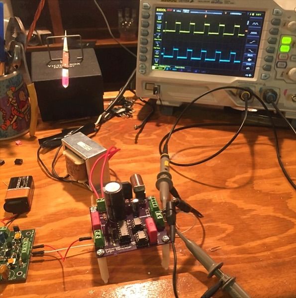
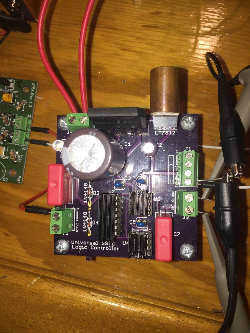
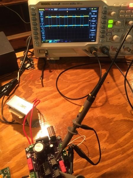
Driver 90% scoped.
I scoped The drive as photo'd with my lead inverted and sure enough the output to the GDT measures 4.5 kHz. With a square wave. @ a hair over 12v

Next I hooked up the probes to the two ICs pins 7 and the neg rail WITHOUT inverting one channel and got a similar waveform. (I'll spare you the duplicate photo but they were the same)
Last 10% are you referring to the 14dip Ic as the Schmidt trigger? Are these steps in reference to ground or neg rail? vv
Quote:
"2) Same square wave at pin 1 of the schmidt trigger IC
3) 12V square wave at pin 4 of the schmidt trigger and pin 2 of the UCCs"
Looks like the driver is working fine.
Next maybe its back to the drawing board on the GDT(15T) and bridge. All the parts are new and should work.


