As I posted above, I believe my meter is pretty close to DTR's. I compared a P73 and a 3W, 9mm diode against his runs of these diodes, posted on his site. My measurements were 10% and 5% lower respectively and that could certainly be partly a diode to diode variation as well as some variation in the meters. CD got almost identical power output/A as I did, but he was able to run his diode up a little higher. My optics free max was 5.6W @4.4A. Even a NIST certified, calibrated power meter will not produce a final benchmark unless 5-10 diodes are tested. These are harvested and the series is evolving rapidly. They may vary significantly.
Now, I am waiting to here what CD's beam manipulation produces, but what about everyone else with one of these diodes? Is the beam as big and divergent as mine (I suspect a defective diode)? Can a lens pair, placed very close to the collimator, better counter the divergence? Do prisms actually work better here than they do on other diodes?
Warning....LONG WINDED READ...grab a beer !!!:drool::drool::drool:
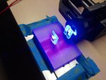
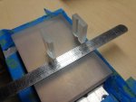
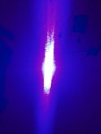
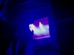
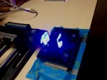
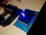
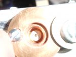
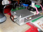
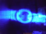
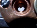
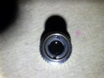
OK....did some quick and dirty tests.....see the pics !!! I placed a set of 6X Cylindrical optics...very, very close to the output of the G2 lens...maybe 2mm distance.
The farfield measurement was approx. 11mm wide by 10mm tall at a farfield target distance of 25' (7.6M). We need to do some masking for there are vertical wings presented when using the CL pair !!
The cylindrical to cylindrical inside plane to plane separation is 28.57mm.
I favor the Cylindrical set correction for it will cause less optical loss than the Anamorphic prism pair set up.
I will measure the farfield again....using the Anamorphic pair. I was in a big hurry when I got a 9mm wide farfield ???
This was a crude set up....but....it is a start in determining if this diode can be tamed !!! At least for use in the HH format....as for Projector use ??? Hmmm??
I measured the nearfield with the above Cylindrical set up... Yikes !!!
The beam presents at about 6.5mm wide....which is linked to the small distance from the first C-lens to the LD output !!!
There exists an inverse relationship !!!=====>
The closer the cylindrical lens set is located next to the LD....the larger the nearfield geometry is and the smaller the farfiels divergence is...So...for the HH application....
who cares what is going on at the nearfield !!! It does not matter !!!!!
BUT...for projector use....we do care !!! a lot.... For our beam must " fit " on the scanner mirrors....and if it is too big....then....we waste precious photons...that fail to strike the scanner mirrors....and slip past on either side !!!
Well....then....you would likely say...." Hey...just use bigger scanner mirrors "
Well...yes....that would make sense !!! BUT....the bigger the mirror....the more inertia is introduced into moving the mirrors....
You must remember...scanner mirrors ...move back and forth....30,000 to 40,000 TIMES............PER SECOND....When you look at them....they are just a blur !!!!!
SO...that is what we are up against....and that is why scanner mirrors are kept as small as possible.....SO....the projector group must be concerned with both the Near field...and Far field beam geometry !!!!
The take away is that this diode will likely not be incorporated into laser projector use....IMNSHO !!! hahaha....
Anyway....it is a start !!! For the HH ( Hand Held). format...this diode can be tamed !!....:drool::drool::drool::drool:
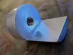
Might I suggest an Aluminum heat sink....with a front semi-circle extension.....and on that extension....two (2) Cylindrical lenses could be epoxy set...at the optimal distance....and a spatial filter (mask) also be placed at the very end to eliminate the vertical wings !!!....just a thought.....search " EZ adaptor " for a visualization !!!...and see the pics I just added below !!!
The final take-away....the beam from this diode is gonna take some..." hammering " to make it presentable ...NOT PERFECT....but....presentable....for my tastes !!!


