Welcome to Laser Pointer Forums - discuss green laser pointers, blue laser pointers, and all types of lasers

Buy Site Supporter Role (remove some ads) | LPF Donations

Links below open in new window

FrozenGate by Avery

NJG-18, multimode boost driver for 445nm.. and possibly 650nm


One of the power handling diodes on these is only rated for about 800mA which is where that number came from. To my knowledge, the drivers that have worked, still work, though I often wonder if this isn't why some people have said they had a lot of issues with dead drivers straight from the supplier. Wonder if those 'pop' as soon as power is applied.
 
Oh, then it's a S8352 using external FET for the switching ? ..... i was convinced it was the S8351, used there .....

If so, it can also be modified for higher currents, i suppose .....
 
well, what sucks is that these drivers have the ss14 diodes which have a max continuous 1A rating, the pulsed rating is like 5A or something really high, but yea, heatsink it or replace it with an ss24 or ss34 and you are golden. 1.4A all day
 
Think I managed to LED my 445nm with the driver, not sure how, the diode is still outputting light, and from what I can tell it's being focused by the lens still but not for any distance.

I'd estimate the power at around kinda 2-3mW? doesn't matter what I do to the pot it won't increase in power (or decrease for that matter)

I'll try hooking the diode upto a flex drive later on I have lying around and see if it works.
 
But, have you modified it for current stabilization ? ..... the driver, "as is", is a constant voltage driver, not a constant current driver .....
 
HIMNL9,
what do you mean current stabilization?? is there more we can do??
I just add a couple solid tantalum caps to input/output, change the ss14 diode to ss24 or ss34, heatsink the FET and the other transistor. I've hit 1.6A on those things pretty stable. Is there anything else?
 
These particular drivers are constant voltage drivers.. NOT constant current. When you adjust the pot on these, your adjusting it's output voltage, NOT it's output current.
 
Ok so I have looked again at running these drivers in parallel and I finally found a combination that I think works. I took two NJG's and used the positive hole for the positive diode wire and the ring around the edge for the negative diode case and negative pin.(this is how I wire them for bypassed modes) I set it to 1550mA and of course by it's self it got very hot very quickly. Now I add a second in in parallel that was individually set to 1550mA and I get a combined 1750mA. But the driver do not get hot. Now the electronics part I am not the best with and I wanted to make sure that this is right before I try connecting them to a diode. Anybody have any thoughts. I am assuming instead of doubling the current like flexes in parallel it sharing the load on boosting the voltage or something. Anyway any input would be great.:beer:
 
This is probly why when both drivers are set to 1550ma out they dont combine and give you 3100ma out instead they share the load so they run cooler IMHO...


These particular drivers are constant voltage drivers.. NOT constant current. When you adjust the pot on these, your adjusting it's output voltage, NOT it's output current.
 
The constant voltage design is why I thought that but just wanted some input before I hooked it up to a diode.;)
 
Last edited:
hmm...1.75A out of njg-18's without the need for heatsinking...combine the cost of two of them they are still MUCH MUCH cheaper than comparable drivers that will probably fry hitting those currents.

good stuff DTR...love your work on these drivers, save myself a heckova lotta trouble. +1 to you man.

EDIT: eerrrr... apparently i must spread some love around first...
 
Last edited:
Don't go too nuts trying it until I put a diode up for sacrifice.:evil:

I am working on building a Saik but the space in between the heatsink and the pill is too short for the driver so I am working on sanding down the pill and with my dremmel and drill it is somewhat slow going.
 
Oh, then it's a S8352 using external FET for the switching ? ..... i was convinced it was the S8351, used there .....

If so, it can also be modified for higher currents, i suppose .....

Hi. HIMNL9.:)

There is the diagram that DTR linked previously at post #98:

Some random thoughts on the NANJG-18 | BudgetLightForum.cz.cc

Is there a way to mod Ra/Rb for higher current(or voltage)?
(R1, R2 and pot in NJG-18)

SHIN

edit] "7N11" written on 5-pin chip of NJG-18
 
Last edited:
I read something about the modification to make it constant current so that adjusting the pot adjusts the current, not the voltage. Is that right? If so, how do we do it?
 
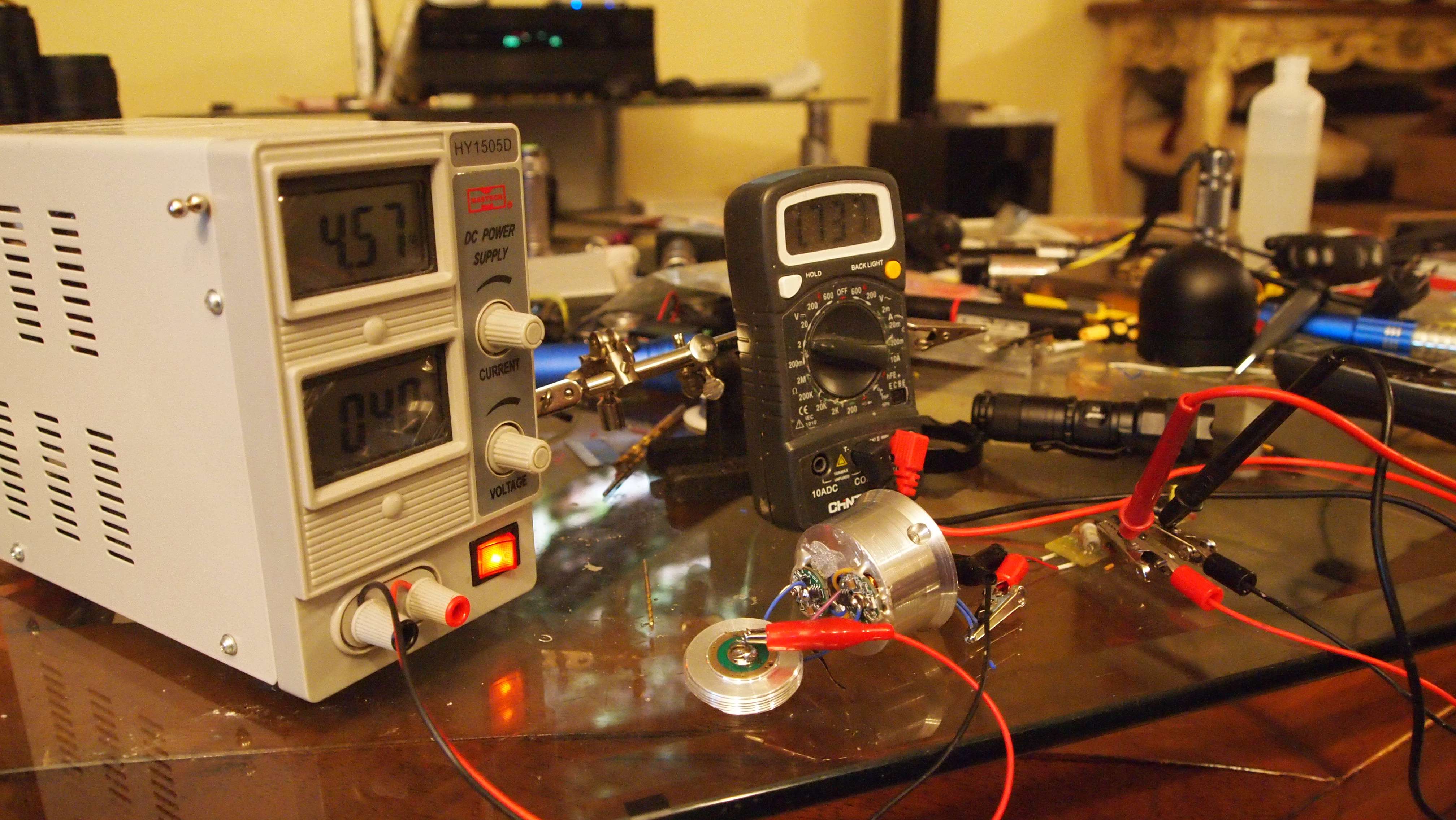
Alright after a small malfunction with a power drill:eek: I am back with some test data. All I can say is I am glad my power source will be a 32600.:eg:


p1015711.jpg


Here is a video. It drops for the first 40 seconds then when the diodes on the test load get real hot it starts creeping back up.


Last edited:


Back
Top