Welcome to Laser Pointer Forums - discuss green laser pointers, blue laser pointers, and all types of lasers

LPF Donation via Stripe | LPF Donation - Other Methods

Links below open in new window

ArcticMyst Security by Avery

Aixiz 50mW ( AT 164mW !!!! )

Joined
Nov 7, 2008
Messages
5,725
Points
0
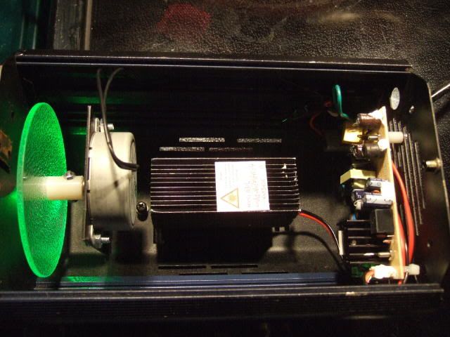
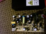
Any pics? Two pot adjustments sounds like TEC cooling to me.. It could be a modulation adjustment, though. Chuck has been known to substitute.
 
Last edited:


Joined
Feb 22, 2008
Messages
3,182
Points
48
ok electro hows this man i hate this new system io hate trying to put in a pic lol
 

Attachments

  • aixis board.jpg
    aixis board.jpg
    127.5 KB · Views: 107
Joined
Nov 27, 2008
Messages
863
Points
18
Looks like a TTL adjustment to me too, although the driver boards look very similar, none of mine have 2 pots, weird. I'm leaning away from a TEC adjustment simply because there isn't an output for the signal/power on the board anywhere...

I'm assuming the one that worked for the output was the one marked #1 on your board, right?
 
Last edited:
Joined
Feb 22, 2008
Messages
3,182
Points
48
Dale thats what i thought it would be too, but vr1 did nothing vr2 controlled the power overall i'm happy and love it i hope Coldstl likes his coldstl where are you lol
come by and pick up your labby
 

HIMNL9

0
Joined
May 26, 2009
Messages
5,318
Points
0
Can you see where this vr1 is connected ? ..... looking the tracks, i mean .....

can be a ramp regulation for a soft-start ? ..... or some sort of overtemp / overload protection ?

Just wondering, cause i don't see a TEC connector on the psu board, at least from that pic.

Can be helpful if you can track down the schematic of that section, or look how is connected to the rest.
 
Last edited:
Joined
Nov 7, 2008
Messages
5,725
Points
0
Deifintely not a TEC.. I'd say most likely it's a modulation level control, but it could be something like what HIMNL9 describes. I'm really not 100% sure looking at that photo, since I can't see the traces.
 
Joined
Nov 22, 2008
Messages
1,267
Points
38
Picked mine up from John, and I love it. I found out the hard way that I shouldn't touch the bottom of the driver when it is plugged in...got a nice little shock.
Would securing a mica plate on the bottom be a bad idea? I don't want to trap any heat, but I'd like to make sure I don't have any shorting problems.
 
Joined
Feb 28, 2008
Messages
1,809
Points
0
ok electro hows this man i hate this new system io hate trying to put in a pic lol

thanks for that pic John. I just bought a very similar labby from o-like and wasn't sure which wire is for TTL and which is for power, I can see that the left one is TTL and right is power from this pic though :)

thanks,
Kendall
 

HIMNL9

0
Joined
May 26, 2009
Messages
5,318
Points
0
You can use mica, if it's a foil hard enough to not break when you move the psu ..... or also one of those plastic foils that sometimes you find inside broken pc psu, under the circuit (it's high density plastic for insulation), and glue it on the back with some points of silicone (no thermal glue, and preferably no "bostik" style glues, that uses flammable solvents) ..... a point in each corners and one in the middle can be enough.

And for the heat exchange, i suggest you to just put some spacers under the pcb, for keep it 5mm over the mica / plastic plate, in waiting for the silicone to be hardened, and remove them just when it's hard ..... this way, when it's hard, your pcb remain lifted from the plate, granting air circulation, and still insulated.

This, ofcourse, if you don't prefer put all in a plastic box with air holes and a little fan ..... remember that not only the back of the circuit is powered, when it's plugged in :D
 
Joined
Jun 17, 2008
Messages
608
Points
0
Can anyone provide me with an email to contact chuck at?

Thinking of buying one but i got stuff to ask first
 
Joined
Nov 27, 2008
Messages
863
Points
18
Coldstl - cmon, man, that's a little more than a "little" shock (trust me, I know ... Sheeeesh!)

Here's a pic of how I mounted one of mine, using both tips above (the nylon spacers and the plastic shield from inside an old cordless phone) ... for safety, while I was moving, aligning, etc I made a simple shield for the bottom out of electrical tape which saved me a few "zaps" in the short term.

lumia_01.jpg
 
Joined
Nov 22, 2008
Messages
1,267
Points
38
@HIMNL9- Thanks for the advice and suggestions.
@BCM- Lol, yeah ok. It was a bit more than a little shock, but not too bad. I like the way you mounted your unit, thanks for posting that pic. I think I'm gonna do something similar and save myself from future "zaps".


Top