Welcome to Laser Pointer Forums - discuss green laser pointers, blue laser pointers, and all types of lasers

LPF Donation via Stripe | LPF Donation - Other Methods

Links below open in new window

ArcticMyst Security by Avery

8X Diode Murder fund

Joined
Dec 6, 2008
Messages
1,581
Points
63
bryce007;

Based on some precautions from the laser diode manufactuers,

I have been using Schottky diodes wired opposite the normal current flow thru the diode.

This limits static discharge to less than 1/2 of a volt in reverse polarity.

Diodes usually have a maximum reverse voltage of a few volts.

LarryDFW
 

Attachments

  • lm317bluray.jpg
    lm317bluray.jpg
    33.5 KB · Views: 391
Last edited:


Joined
Jul 1, 2009
Messages
1,679
Points
0
bryce007;

Based on some precautions from the laser diode manufactuers,

I have been using Schottky diodes wired opposite the normal current flow thru the diode.

This limits static discharge to less than 1/2 of a volt in reverse polarity.

Diodes usually have a maximum reverse voltage of a few volts.

LarryDFW

That sounds like a good idea, thanks!
 

IgorT

0
Joined
Oct 24, 2007
Messages
4,177
Points
0
Couldn't do this sooner, too busy..

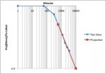
Here are the 60h degradation plots:
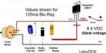
attachment.php


attachment.php


Diode Stats:
- Ith = 37mA
- Po @ 300mA = 330mA (92.7% of initial power)
- Slope Efficiency = 1.254mW/mA
- Actual Efficiency = 18.81% Peak / 18.51% Avg.


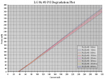
Degradation has slowed down to a point, where it's hard to discern PI plots, even tho almost 20h passed since the last one.

The slope efficiency was actually calculated to be the same as before. The only reason the new plot ended somewhat lower is, that Ith was measured higher than before.
Basically, the slope is the same as before, only difference is, that the entire plot is shifted to the right by 1mA....

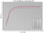
Interestingly, the efficiency plots show much more of a difference, but i should mention, that the previous one (yellow line) doesn't fit in.

This is most likelly due to temperature differences. It resulted in some errors, that are hard to explain.

The temperature was higher when i recorded the 42h plot - 26°C instead of 21°C. This should have resulted in a lower efficiency. But the Vf drops first as the temperature climbs, while the power drops much more slowly. Due to a lower Vf, the El. input power was lower, while the output power was almost the same, so the calculated efficiency actually came out higher!

This is somewhat confusing, i'd expect it to be the other way around...
I'll have to do some plots of a healthy diode at different temperatures, to explore this behavior in more detail.


Anyway, this is it for now, the diode is still alive and well. I might have to spread out the re-plotting intervals even more, to detect measurable differences next time.


Back to work for now, otherwise i'm getting parts to expand the torture chamber tomorrow...
 

Attachments

  • 60h LG 8x #3 P-I Degradation Plot.PNG
    60h LG 8x #3 P-I Degradation Plot.PNG
    81.1 KB · Views: 241
  • 60h LG 8x #3 Efficiency Degradation Plot.PNG
    60h LG 8x #3 Efficiency Degradation Plot.PNG
    75.1 KB · Views: 288
Joined
Feb 5, 2009
Messages
114
Points
18
It looks like each step down it power output takes twice as long as each previous step.

I think that there is definitely something else in the die that is degrading besides the front facet...
 

CHP

0
Joined
Sep 30, 2007
Messages
74
Points
8
latest degradation plot
 

Attachments

  • las60hr.jpg
    las60hr.jpg
    20.9 KB · Views: 87
Joined
Feb 5, 2009
Messages
114
Points
18
It looks like it is beginning to curve out again near the bottom. Probably that means it is beginning to enter the last phase of degradation before it pops.... just my opinion...
 

daguin

0
Joined
Mar 29, 2008
Messages
15,989
Points
113
It looks like it is beginning to curve out again near the bottom. Probably that means it is beginning to enter the last phase of degradation before it pops.... just my opinion...

That assumption appears to be absolutely random. What causes you to think this?

Peace,
dave
 
Joined
Feb 5, 2009
Messages
114
Points
18
The first 3 or 4 points of data in CHP's graph have a downward curve until the actual data line matches the projected line. Then the last three points start to curve outward again slightly, indicating that the degradation is slowing down less than it was before. Does that make sense? At least, that is the way I interpreted it....
 

daguin

0
Joined
Mar 29, 2008
Messages
15,989
Points
113
The first 3 or 4 points of data in CHP's graph have a downward curve until the actual data line matches the projected line. Then the last three points start to curve outward again slightly, indicating that the degradation is slowing down less than it was before. Does that make sense? At least, that is the way I interpreted it....

That is a fair description of what is happening. My question is about why you think that this "flattening out" indicates the end of the diode? AFAIK we have never observed this before. The facts are not being questioned. The interpretation that this is "the last phase of degradation before it pops" is.

Peace,
dave
 

HIMNL9

0
Joined
May 26, 2009
Messages
5,318
Points
0
25mW down from 0-60... is that good, great, ...or bad?

Uhm ..... depend ..... 25mW of loss on that power, in all that time with the diode overloaded, looks good ..... but the real question may be made if it is good or bad respect what, exactly ? ..... i mean, this is the first diode cycled and plotted so long time (at least, the first one for which we have data), so we don't have any other data to compare with this one and try to guess ..... if the next one die in 10 hours, these results are good, if the next one last the double or loss half of this, the result is bad ..... just not enough data, for now .....
 
Joined
Dec 6, 2008
Messages
1,581
Points
63
Traveller;

The laser diode manufacturers consider end of life,
when it takes 30% more current for the same maximum pulse output power.

At 60 hours, we are only requiring about 8% more current for that same maximum pulse output (250mw).

So it looks like the diode should easily make 100 hours at this point.

Very good results, considering we are overdriving the diode by about 50% more than peak current
(300 vs. 200ma).

LarryDFW
 
Last edited:

daguin

0
Joined
Mar 29, 2008
Messages
15,989
Points
113
Traveller;
The laser diode manufacturers consider end of life,
when it takes 30% more current for the same maximum pulse output power.
At 60 hours, we are only requiring about 8% more current for that same maximum pulse output (250mw).
So it looks like the diode should make 100 hours at this point.
Very good, considering we are overdriving the diode by about 50% more than peak current
(300 vs. 200ma).
LarryDFW

And this is what we consider to be the worst diode of the bunch :D

Peace,
dave
 
Joined
Feb 5, 2009
Messages
114
Points
18
That is a fair description of what is happening. My question is about why you think that this "flattening out" indicates the end of the diode? AFAIK we have never observed this before. The facts are not being questioned. The interpretation that this is "the last phase of degradation before it pops" is.

Not "the end". It could very well last quite a while longer than it already has. I suppose I just meant that I didn't think the "slowing down" would increase again...
 

IgorT

0
Joined
Oct 24, 2007
Messages
4,177
Points
0
This diode has it's mind set... It won't give up any time soon!

It just reached 90h this moment. Waiting for it to cool off for re-plotting.. :yh:


Top