xStatiCa
0
- Joined
- Feb 7, 2010
- Messages
- 360
- Points
- 0
I wonder how long will it run at that amperage in a closed area (like in a host).


Follow along with the video below to see how to install our site as a web app on your home screen.
Note: This feature may not be available in some browsers.


")
 Ill try replacing it today.
Awesome! Congrats.
I got my station and parts yesterday ... I think I managed to kill the TI chip
What have you done wrong?
How did you soldered the other boards?
I did them by hand with two soldering irons. For the QFN I put a small pillow of solder on the chip's thermal plane and the pin pads on the board. I heated the ground plane on either side of the chip until it reflowed into place. Then I did the blob meathod to reflow the solder on the pads.
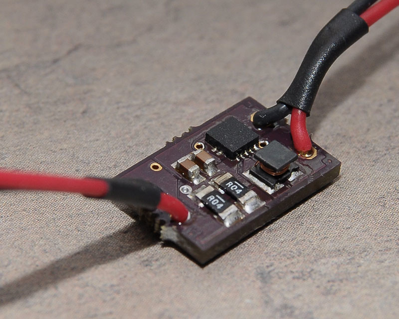
Success. Measured 1.14 Amps w/ 4V dummy load! Temp only 49ºC(120ºF) @ about 30 seconds. Hell yeah!
I had to replace the TPS ... luckily I ordered 3. I transplanted everything to a new board and did not use paste. I pillowed the pads with regular 60/40 solder applied flux and gently put the parts on top. I used higher temp but held the air nozzle further away and it re-flowed perfectly. The joints are all so perfect.
jib77;
Good job on the new board.
I have some quality #18650's if you need some to try.
I live in Farmers Branch.
LarryDFW
congratz!
well, looking at the inductor I see that is not possible to put an effective heatsink, because the inductor is somehow tall..
will it pump more current? heatsinking? maybe adjustable output (pot)? ^^
hell yeah, gratz again