- Joined
- Apr 27, 2011
- Messages
- 162
- Points
- 18
minimum 200mw? or does it just mean it works best >200mw??


Follow along with the video below to see how to install our site as a web app on your home screen.
Note: This feature may not be available in some browsers.


I'm going to take the plunge and grab one.
I've been searching for the last 20 or 25 minutes to find a similar LED panel in blue instead of red. I couldn't find one with the appropriate resolution. If anyone happens to have found one, know of a link, let me know. I'm going to place my order in ~30 minutes. Going to search for a nice housing first")
Here is the Same One Iam Useing on my 5W one.
4-1/2 Blue LED DC 20V Digital Volt Voltage Panel Meter | eBay
Perfect for an OPHIR Head.
I saw that one to, but the "0.01V" resolution (10mV) scared me off. Think that's a typo?
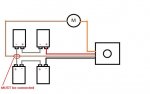
Here is a diagram 300EVIL over @ PL made for me. You can use 2 9V batteries instead of four like the picture or you can replace them with two 12V out DC-DC converters as I did. :beer:

As shown that drawing does not work....
Jerry
Thanks...:beer:What an insightful post.
?
NOS=New Old Stock... :crackup:
The heads were actually New Surplus unused heads.
DTR has the correct link for the new Calibrated ones..
What draws the majority of the current is the converter
if used and the LED DPM...
An LCD type would no doubt draw less current..
You are still correct.. It is a Digital Panel Meter (DPM) that
just happens to be a voltage measuring type...
Jerry
The panel meeter draws 90mA. So that leaves 40mA being drawn by the head and the converters. I prefer the LED as it is much better for making LPM videos for my tutorials or customers.
Here is the one I ordered. If you get something similar read the description carefully they have ones that look identical but some don't have the same resolution or range.
This is a 20V range with 1mV resolution.
4 1/2 Digital DC20V Voltage Panel Meter Voltmeter | eBay
Here is a diagram 300EVIL over @ PL made for me. You can use 2 9V batteries instead of four like the picture or you can replace them with two 12V out DC-DC converters as I did. :beer:
The drawing does not show the tap for the virtual ground at +18VDC.
The drawing does not show the tap for the virtual ground at +18VDC.
Well, there's no power supply going to the meter itself, but I wasn't considering that a flaw. I presume the drawing left that out intentionally.
")