Welcome to Laser Pointer Forums - discuss green laser pointers, blue laser pointers, and all types of lasers

Buy Site Supporter Role (remove some ads) | LPF Donations

Links below open in new window

FrozenGate by Avery

Tiny RGB

I didnt regrind the optical surfaces. I just cut it in half and ground the freshly cut face smooth.
Yeah, that's what I meant. It's cool that you got acceptable surface quality - it's something I've wanted to try but figured it's not worthwhile considering the stone-age tools I'm working with.


Its relativly easy. Just use a diamond cutting tool. China sells cheap files for like 5$ a set that work well.

Update:
I managed to fuck and unfuck the board.
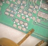
Starting with printing paste before placing components and soldering:

paste.jpeg

The two wires on the bottom left are again for size comparison. Thats a 9mm Diode.
The pads are tiny!

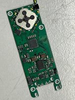
After soldering:
soldered.jpeg

Nice and neat.

I started by applying voltage to the USB port and heard a faint pop. Oh No!
What happend?

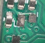
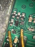
burned.jpeg

Its hard to spot but the rectangular componentin the middle got a hole.

Why?
Because i fucked up and made a mistake while designing the board. The small squares are switches and have its pinout rotated 90°.
That causes a short and burned up the bigger rectangular mosfet.

How to fix that?
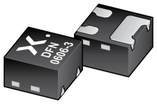
Turn the part 90° and hop that the pads dont short. It got 3 legs so its not symetrical.
sot8001_3d.png


repaired.jpeg

Looks like we have success!
Not nice but it works!

Again, just mindblowing how small that stuff is. The golden pins are again connection leads from a 9mm diode.

Now onto programming. That will take a while!
 
I'd pull all the hair out of my head trying to fix that component
 
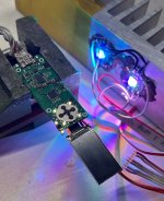
After spending like 4h yesterday night, I manage to finally configure PlatformIO + GitHub for my custom board and started to see signs of life!

I am still using LEDs as a test load to not have to deal with lasers and frying diodes while programming.

signs.jpg

So far I tested:
Buttons ✅
Energy management ✅
Charging ✅
Battery Protection ✅
LED Backlight (Button + LCD) ✅
RGB Laser Drivers 1/2 ✅

Need to check:
Display
Battery state measurement
Temperature measurement
Laser Driver modulation


Wish me luck guys!
 
FINALY!


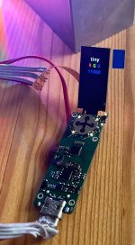
display.jpg

I finally got the display and all the PWM channels working.
PlatformIOs non-support for my board messed me up good. I was already investigating options for rewireing some pins because i could only got the native uC pinout to work. Nevertheless after spending the night googeling and hacking, i found the issue.

We now have:

Display ✅
Laser Driver modulation ✅

Sadly, the driver chip isnt as good while modulating as the datasheet makes it look. I might run into problems with the blue diode being instable at threshold which would be deal breaking.
Red and green should work flawlessly as i can get currents well below threshold.
The blue diode has eceptionally low threshold, measured at 17mA. Driver seems to start behaving at roughly 26mA which would be too high.. (it should start at 15mA - maybe i can replace the component and hope for a better one)

I might need to hack something to waste 10-15mA to get the diode current below threshold.
Its no super difficult, just a parallel resistor, but that always wastes 90mW when the blue diode is running.
90mW doesnt sound like much but that will increase the losses of the blue driver by 70-80%.
And with the whole thing just using <2,9W at full output, 90mW is already >3% of the full energy usage of the unit.
Not happy but not a deal breaker.
 
Lets do an update.

I started programming, made the battery charging screen which gets shown while the unit is plugged into a USB-C charging source.


CHarging1.jpeg

The screen is rather simple, it just shows a battery that slowly fills up and changes color to reflect battery state.
It also shows the current voltage of the cell. Not needed but interesting.

charging2.jpeg


I spend a few hours making and testing a few keylock screens.
Nothing worse than having 500mW burn a hole in your pocket.

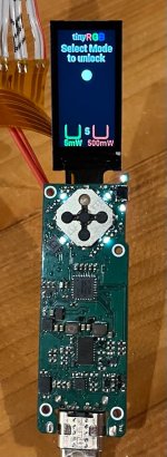
The unit turns on if the fire button is pressed. It than shows this screen:
keyLock1.jpeg

A timer (5 on this image) starts counting down. You have time to manuver the white ball into the pocket at the bottom of the screen.
The logic is: random key presses wont be able to hit the target accuratly before the timer runs out.
This also ensures that you only get the powerlevel you want. If you put the ball into the 5mW hole, the pointer will restrict itself to 5mW max output power.
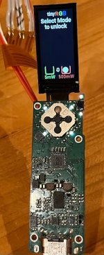

keylock2.jpeg

If you managed to do it before the timer runs out, you will get to the menu screen (which i still need to make).
From there on you will be able to select a few operation modes. Like RGB mode:
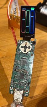

RGBselector.jpeg

This mode shows three bars and let you choose a color based on the standard RGB system.
The D-Pad is used to select which color you want to adjust and you can move the silder with the up and down buttons.

I will also make a few other modes:
- Automatic -> configurable color changes
- HSV color selector
- Presets
- ?

(dont ask how i managed to mess up the UP button on the d-pad ... Its not meant to be pressed with pencils)
 
Last edited:
RGB Test
Now running from battery, still with leds instead of lasers but thats very convinient for software development.

Video
 
This project is so cool! I cannot believe how skilled and talented you are!
Keep us updated! :)


Back
Top