Welcome to Laser Pointer Forums - discuss green laser pointers, blue laser pointers, and all types of lasers

Buy Site Supporter Role (remove some ads) | LPF Donations

Links below open in new window

FrozenGate by Avery

The New Buck/Boost High Output Driver


It's possible to redesign it that way, you know. You could even stick on some copper foil (apply some insulation first) and connect it to the VIN.
 
That's a shame. No battery contact for positive?

believe it or not it would have been a shame if there was ;)

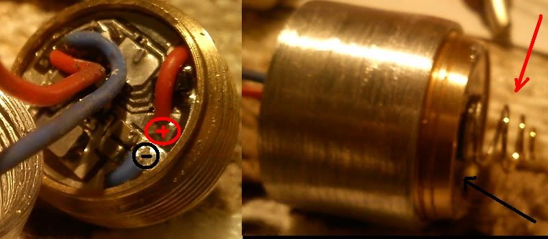
check the photo again - the driver is mounted on the top side of the pill. So, that the bottom of the driver is heatsinked on the pill. There are two holes for wires for the positive and negative. Or you could just use one as the ground is taken from the pill.

I don't see why a battery contact is necessary as you can easily do that so many ways. For example take a ~16mm driver board from any cheap DX driver ($1.5) strip all the components and use that on the other side of the pill like I did with my 445nm build. You can attach a string for battery contact and run the wire from the top side of the DX drive through the pill's holes and solder it on the positive input of my driver.

preatty easy to do..

having a contact on the driver itself wouldn't be a good idea as most of the surface of the driver will be hanging and poor heatsinking will occur also the IC would be right above the battery contact. Not good.

Anyway I hope you understand that approach I explained. If not check the photo attached. :beer:

temp.jpg

the spring is attached to the second bare board on the bottom of the pill ;)
 
I wouldn't try that :D

Why? Sorry if I explained that wrong...
Step 1) cover the bottom of the driver with black/clear insulation tape
Step 2) stick some copper tape on the insulation tape as the positive battery contact
Step 3) connect the copper tape to the voltage input

That should work too, won't it?
 
dude have you read my recent posts - the boards are in production should be ready soon :) if you would like I will PM you when they are ready :beer:

Nop, Just skipped to page three :p

Cool! I need one for a saik :)
 
Why? Sorry if I explained that wrong...
Step 1) cover the bottom of the driver with black/clear insulation tape
Step 2) stick some copper tape on the insulation tape as the positive battery contact
Step 3) connect the copper tape to the voltage input

That should work too, won't it?

yeah it would but you lose the heatsinking that way and when the driver gets hot enough the tape will melt and make a short.... not a good idea if you ask me ...

the best way is to use my method IMO. :) :beer:
 
Oh... yeah... heatsinking... You can tell me about that... once my design got hot enough to desolder a wire that was attached to it.
 
Well, Foulmist, then there is a problem if your design requires so much heatsinking =p It's a good design, but it's not optimal, especially for the premium you are charging ;)

The reason I asked if it was one-sided with a PCB + contact on the bottom was to see if I could use it in my builds. My custom heatsinks that I make generally have a 16.4mm area bored out for a driver to attach directly to the heatsink =p

I'm not very experienced in this area yet, but couldn't you just put this driver in your sink and just change the polarity of the case? Making the case neg instead of pos or whatever?
 
Well, unfortunately, no, because these drivers regulate along the positive rail, so if positive is continuous, then they will just be direct driving.
 
Well, Foulmist, then there is a problem if your design requires so much heatsinking =p It's a good design, but it's not optimal, especially for the premium you are charging ;)

The reason I asked if it was one-sided with a PCB + contact on the bottom was to see if I could use it in my builds. My custom heatsinks that I make generally have a 16.4mm area bored out for a driver to attach directly to the heatsink =p

I don't think there will be a design this small that will not be required to be heatsinked at 2A of current. ;)

When I put it in my host attached to the pill it can stay on for over 5 minutes at almost 2A without getting hot I so think it's ok. :)

If you can make a non heating driver at those currents - congrats :D

I agree. Think about it conceptually Wolf -

If you're doing 2A and ~5V (at that current) for a 445, you're looking at 10W out of the driver / into the diode.

Assuming ~80% efficiency, which I think is probably a reasonable target for most boosts delivering this current level, you're looking at about 2.5W of losses, which really just means 2.5W of heat dissipated by components. When you're dealing with relatively small SMD components (as opposed to T0-252 or TO-263 linear drivers), you just don't have the "built in mass" to absorb much of that heat right off the bat. You're almost always going to need *something* to eat up that heat.
 
That. Imagine pointing a 2.5W laser (well, more than 2.5W to be exact) onto it. Hot, right?


Back
Top