Welcome to Laser Pointer Forums - discuss green laser pointers, blue laser pointers, and all types of lasers

Buy Site Supporter Role (remove some ads) | LPF Donations

Links below open in new window

FrozenGate by Avery

The New Buck/Boost High Output Driver

WoaH !! Dude, You did it.. Now thats some driver your making ..Whats the Official Launch date?! ;)

no official date yet.. I have to figure out why efficiency drops. I did some tests with the test load efficiency is 20% higher at the same voltage and current. O.o but when I hook it up to the diode efficiency drops? :wtf:


The silicon diodes just give a reference idea of the test load , in order to simulate it you should try a 445 diode which is previously damaged into led.. iirc it is the best way to measure!
 
The silicon diodes just give a reference idea of the test load , in order to simulate it you should try a 445 diode which is previously damaged into led.. iirc it is the best way to measure!

I use my 445nm laser diode which is alive :D for the real testings ;)
 
Thats somewhat not a wise thing , not recommended either, why would you use a perfectly fine diode as a test load, Things are most likely to go wrong when prototyping.. there is a 50 50 chance that the prototype works according to calculations, almost everytime somethings missed out or is calculated wrong and PUFF! the diode flickers and there it goes..becomes "led".. i never do that to an alive diode, Its almost like killing a living thing :P !!
 
Thats somewhat not a wise thing , not recommended either, why would you use a perfectly fine diode as a test load, Things are most likely to go wrong when prototyping.. there is a 50 50 chance that the prototype works according to calculations, almost everytime somethings missed out or is calculated wrong and PUFF! the diode flickers and there it goes..becomes "led".. i never do that to an alive diode, Its almost like killing a living thing :P !!

Lol :D I guess I didn't say it right.

I first always do tests with TEST LOADS(I even use incandescent bulbs 5.2V as test loads). Also, I check the output on Oscilloscope. After I see a steady output I do the real tests with an alive diode. I can risk the diode but if I don't make that test I cannot be 100% sure it works. :beer:
 
Thats somewhat not a wise thing , not recommended either, why would you use a perfectly fine diode as a test load, Things are most likely to go wrong when prototyping.. there is a 50 50 chance that the prototype works according to calculations, almost everytime somethings missed out or is calculated wrong and PUFF! the diode flickers and there it goes..becomes "led".. i never do that to an alive diode, Its almost like killing a living thing :P !!

I'm sure foulmist is perfectly capable of evaluating whether he wants to use his live diode to test a boost driver once it has obtained the basic test-load's approval ;)

And where did this "50/50 chance of working as per calculations" figure come from? Is that in the datasheet? ;)
 
Last edited:
I guess protected cells should be used instead of non-protected with this IC.
I can't see a way to modify the undervoltage lockout threshold - it's set to 1.6Vmax. It can be made with sensing the input voltage and controlling the EN pin but that will take way more space.

foulmist;

I would not worry about the low voltage cutout.

I have tested U.L. name-brand cells repeatedly to that level, without any cell failures.

Overall driver efficiency improvement is desirable.

LarryDFW
 
Last edited:
I'm sure foulmist is perfectly capable of evaluating whether he wants to use his live diode to test a boost driver once it has obtained the basic test-load's approval ;)

And where did this "50/50 chance of working as per calculations" figure come from? Is that in the datasheet? ;)

yep, thanks rhd :) :beer:

foulmist;

I would not worry about the low voltage cutout.

I have tested U.L. name-brand cells repeatedly to that level, without any cell failures.

Overall driver efficiency improvement is desirable.

LarryDFW

I figured out why my efficiency was so low - the DMM as A meter in series with the diode to check the output current was messing it. Without the DMM I got 75%, which has to be improved further but that's a LOT of relief. It's one thing to go from 60% to 85% and another is 75% to 85% :D.

and btw people you can refer to me as Tom :D ..

-Tom :D
 
Lol :D I guess I didn't say it right.

I first always do tests with TEST LOADS(I even use incandescent bulbs 5.2V as test loads). Also, I check the output on Oscilloscope. After I see a steady output I do the real tests with an alive diode. I can risk the diode but if I don't make that test I cannot be 100% sure it works. :beer:
Yes Offcourse you do! I Just thought the way you are saying implied that..
But my bad!!
I'm sure foulmist is perfectly capable of evaluating whether he wants to use his live diode to test a boost driver once it has obtained the basic test-load's approval ;)

And where did this "50/50 chance of working as per calculations" figure come from? Is that in the datasheet? ;)
Well we must congratulate him nevertheless, he's making something "urgently needed" for higher power 445's and i envy him!!
50/50 is not actually the same all the times, sometimes you get lucky..and sometimes it strikes back so just a stereotype for things that dont go right everytime..
P.S: Is my english too bad!!? lol ;) :beer: Cheers!
 
Last edited:
UPDATE:

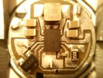
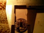
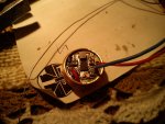
I made the board 16.3mm which will fit most driver pills found in flashlights. I think that's the perfect size. Here are some photos of my final design..

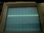
I added a 2.9V input cut off voltage protection. I tested it up to 2.1A in boost and 2.5 in buck mode. A scope photo as well with no pulsations that I can see.

Efficiency is around 75% at 3.6Vin, 4.5V@1.8A out - I tried to get it higher but I couldn't so I will leave it that way. Heatsinking is a MUST from the bottom said of the driver.

It has two holes on the pcb for the wires of the input. Current is set by a fixed resistor. 0.5 / R = I

0.1/0.5% tolerance 1206 2X resistors in parallel are recommended.
High Capacity, High quality Li-ion battery required!!.

Not the best driver there is but anyway tell me what you think ? :)

Thanks
-Tom
 

Attachments

  • DSC00095.jpg
    DSC00095.jpg
    212.8 KB · Views: 908
  • DSC00096.jpg
    DSC00096.jpg
    203.7 KB · Views: 368
  • DSC00098.jpg
    DSC00098.jpg
    192.2 KB · Views: 404
  • DSC00101.jpg
    DSC00101.jpg
    122.3 KB · Views: 359
Last edited:
Very good job on the drivers man.The efficiency is very good,Whats the cost of this praticulasr one?I will be very happy if you send me a review unit :D:D.Keep up the good work buddy:worthy:
 
Very good job on the drivers man.The efficiency is very good,Whats the cost of this praticulasr one?I will be very happy if you send me a review unit :D:D.Keep up the good work buddy:worthy:

This particular one costs a fortune :D:D:D I spend over 70 bucks for parts which I don't need til I choose the most appropriate ones :D not to mention the copper boards which I used a lot till I get a the final design and the time too :D:D

But If there is interest in buying this driver I can make complete boards for about <$40 I think maybe less ..... I have to check what will be the pcb costs on these.

I will solder and test each one by hand. :D
 
Finally , This is a great achievement +1
Quick question: $~30 doesnt mean $29.99!! Right? :thinking:
 
Last edited:


Back
Top