Welcome to Laser Pointer Forums - discuss green laser pointers, blue laser pointers, and all types of lasers

LPF Donation via Stripe | LPF Donation - Other Methods

Links below open in new window

ArcticMyst Security by Avery

The Green Gargoyle 10.08 W @ 520nm

Joined
Feb 25, 2010
Messages
1,643
Points
113
HMMMMM ??? What other group of Technology / Users is obsessed with heat removal ....Overclockers !!! SO...I will see what they say ????? Aside from Liquid Nitrogen cooling.....For starters.....They seem to like this fan......


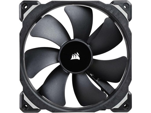
SO....High Static Pressure is mentioned. I will continue to investigate and study what the Overclocker group sez........Obviously....this is a huge area !!!
….and I am truly a Stranger....in a Strange Land !!!

Bob


Joined
Feb 25, 2010
Messages
1,643
Points
113

Hmmmm....Smaller....3" OD x 5" long !! What CFM at what static pressure ???? 0.2 inches water column ?????
0.1 inches water column ??? What RPM ??? Likely a 12VDC driven !! Not much info given !! This is used in the Auto industry !!! So....maybe a candidate ?? Soooo much to learn in this area !!! Liquid Nitrogen s look'in better !! hahaha

Bob
 
Joined
Jan 29, 2014
Messages
12,031
Points
113
I like the look of that fan you found, need to see what the specs are, is that not too big? We can make it smaller by removing the white plastic shroud it is mounted in and use the host walls in its place.


Edit: Found them, specs for the above fan: https://www.boatid.com/attwood/12v-...lge-blower-mpn-1733-4.html?singleid=800292790


I agree, just take our best stab at it and the results will be the results. Best stab I can make is to use the highest RPM fan which can withstand the highest back pressure we can find at a reasonable cost which does not impact the dimensions of the host too much. We can run the voltage lower to reduce the power draw, noise and airflow, if needed. We just need to make sure there is also enough aluminum mass in the head to be able to sink heat for a period of time without worry, doing that and adding a fan and we should be good.

I can try two of these server fans in series, since they each already have two fans in series in them, that ought to give us as much pressure as possible in this size of package, the total length of the two fan assemblies together will be about 110 mm, maybe that is too much? I might be wanting to do too much with two, one of these series fan assemblies might be enough. I will test and see with a mock approximation of the resistance we will have using a cardboard mock up.


Since we are on a new thread page, here is a photo of the series server fan I found and will be testing soon.

 
Last edited:
Joined
Feb 25, 2010
Messages
1,643
Points
113
Thanx Chris....Yes....the build size is growing...but....that is not unexpected when dealing with Six (6) LD in a single unit !

MMmm...We may have to incorporate the LiPo cells in a stand-off unit....that may double as a handle. Depends.... if we want to grow in a linear or radial direction Will continue to study.

Yes....Looks like we could hack the AllStar ducted fan....remove the white shroud...and insert into the Aluminum host. Should result in less space for the fan !! Another off-the shelf source of Ducted fans....again....the RC hobby !! They use Ducted fans for some RC planes....and they are obsessed with maximum Static pressure....for that is what delivers maximum speed and maneuverability….I think !!! Just another avenue !!

Two fans in series may also work.... Thanx for your help. We are pushing the envelope...in our small way.

Bob
 
Last edited:
Joined
Feb 25, 2010
Messages
1,643
Points
113
Yikes....Just type in " rc ducted fans" to Ebay….555 listings.....Hmmmmm….That is likely where our solution lies. These fans kick out some serious wind....if it is enough pressure to push a RC plane at 75 MPH....it sure should be overkill to cool our Hex Core !!!! And...there are a Gazillion sizes !!! Thanx...RC boyz !!!....And...this format fits our Aluminum 3.75" ID Host !!! Hmmmm....we can have our cake....and eat it to !!

Bob
 
Joined
Feb 25, 2010
Messages
1,643
Points
113
OK......I select this EDF ( Electric Ducted Fan )…..


Per RC Groups Forum....most quiet unit on the market with 2700G thrust !!! ( Likely due to the precision balancing)…. That is surly enough Static Pressure.

This might be Overkill....MMMM....Could Be....but....it is not going to be under powered….that is for sure....We will need an ESC to control the speed....

I imagine we may only run at 50% fan capacity....but that will mean even less operational noise !! All EDF are very high RPM....and a great deal of Static pressure / Thrust !!!

OK...Bigger than I would have liked....But.....Ya just cannot have it all !!!

Wow...A 6S LiPo cell pack is required for this fan !!!!.....about 6" x 2" x 2"....MMMMMMM Well.....THAT LiPo pack will also power the LD's....with a Step Down VC !!!!

Where am I gonna put all this stuff ??????? Maybe like the CC build ??? See Pic....LiPo cell go in a box atop the build....which also forms a handle ????

Well....that is just the way it is ~~~ Six pointers bundled into one.....have a price !!!

Later,
CDBeam
 

Attachments

  • CC Ortho view no components.jpg
    CC Ortho view no components.jpg
    128.7 KB · Views: 3
Joined
Jan 29, 2014
Messages
12,031
Points
113
Holy rat tails Batman, that thing draws a lot of current at full speed, wow. I am interested in how slow we can run it and still produce enough CFM of air at reduced current.
 
Joined
Feb 25, 2010
Messages
1,643
Points
113
Hahahahaha..." The answer my friend....is Blowing in the wind " !!!!!!!!!!!!!!!!!!! ESC will take it all the way down....0 - 100 % How much wind....I have NO idea....BUT....we will have enough !!!!

Note: NO other comments necessary from other members about my personal supply of wind....such behavior....is just beneath you !! TOooo easy !

Added: Improved pic of approx. final artistic concept ….would look simular…...But...Aluminum barrel would be extended all the way to the back and EDF Shroud / EDF cowling would be extended out about 10mm from the rear of the build.

Bob
 

Attachments

  • Green Gargoyle with Handle 1.jpg
    Green Gargoyle with Handle 1.jpg
    128.2 KB · Views: 3
Last edited:
Joined
Sep 20, 2013
Messages
17,424
Points
113
I hope so! At 68 amps at 25 volts that consumes 1700 watts. More like the power consumption of a blow dryer.
 
Joined
Dec 9, 2011
Messages
221
Points
28
When I've had to design something with thermal management in mind, be it a heatsink with fan or TEC, I start with heatsink calculators on the web. This is a good place to start if you know the heat input in watts to the heatsink. Some of the more advanced calculators even do pressure drop, CFM, etc. Because there are a lot of variables the calculators only give a starting point. Next I will usually mock up the heatsink and fan with a dale aluminum resistor in place of the heat load. Its real easy to "dial-up" the wattage on the lab supply to approximate the heat load in watts. Then measure the increase in heatsink temp from ambient over time. Once the temp stables out you're at the delta T. Other factors apply, like the thermal resistance of the mount to the heatsink, etc. Usually I omit this or leave a few degs for fudge room. With properly fitted copper mounts the Delta T is really pretty low at that interface. Generally the more fins the better, however the width, height and gap make a big difference on the efficiency and pressure drop. I think in your case the matting of the fins to the wall of the hex piece is the most important. If its not in perfect intimate contact they will be pretty worthless. I would probably bore the hex piece on the lathe making sure my tailstock is perfectly aligned. Them turn the the heatsink fins to maybe .0005 bigger than the borehole. Put the fins in the freezer and the hex part in the oven. Hopefully they will slip together. If not then press them together. Most extruded Al heatsink is really soft. So that should help.
 
Joined
Feb 25, 2010
Messages
1,643
Points
113
WOW...I have seen the heat / cool technique done in an Industrial setting ….Works perfect !!! Thanks for that tip !!! I agree 1000% ….that intimate contact will be critical here to move the heat load into the Extruded Fin stock....then out the unit exhaust ports !!!

I will machine the Hex Bar stock central Axis hole with a boring tool.. The bore hole will be sized to be .0005" smaller than the Extruded material My new Lathe has a massive 4 Jaw chuck....that I will make sure the Hex Bar run-out is as close to perfect as I can get it !! SO....the Extruded Fin geometry sets the Central Bore hole diameter.

Thanx LS for reminding me about the Heat/Cool method. If machined properly....Intimate contact will be achieved !!!

As to the EDF choice.....well....we have 95.250mm ID to fill up. We could go a EDF lesser OD ??? But Why ???.....I would rather go with an excess degree of thrust...then have too little. SO....we dial the EDF speed now.....maybe even 30% of maximum....less power consumption....and less noise !!
For now...I will stick with the

ttp://www.fmsmodel.com/fms-70mm-platinum-series-12-blades-edf-with-3060-kv1900-motor-6s

LS... .... I will study the great info you provided.....Perhaps there is a superior choice....and yea Paul….This Bad boy sucks the juice !!!!

As we evolve the build, I am more convinced we will need to use a stand-off design to accommodate the LiPo cell Pack.

Thank you all for the support....after all....this is a great community effort....and I very much appreciate your support !!!

CDBeam
 
Last edited:
Joined
Dec 9, 2011
Messages
221
Points
28
oops I goofed the order up a bit on my typing. I meant set the tailstock perfect to take a pass on the finned heatsink not the bore operation. The .0005 is just a guess. Maybe even .001 will work. You will have fun chucking up that hex piece👺 Or just buy a 6 jaw chuck. Haha kidding (go check the $ on one for fun).
 
Joined
Feb 25, 2010
Messages
1,643
Points
113
oops I goofed the order up a bit on my typing. I meant set the tailstock perfect to take a pass on the finned heatsink not the bore operation. The .0005 is just a guess. Maybe even .001 will work. You will have fun chucking up that hex piece👺 Or just buy a 6 jaw chuck. Haha kidding (go check the $ on one for fun).


Well.....LS....would it not be very difficult to lathe the Extruded Aluminum units ???? The fins will flex....and...well...the work piece....even if secured with a live centre...I would think the work piece would chatter horribly ???

SO...Why not....bore out the Hex Bar....undersized by 001" ~ .0005...…. using the Extruded Aluminum unit as a guide for the bore dia ???

Then.....use the Hot/Cold method...and get an intimate contact condition ??

I agree setting the Hex bar for near perfect run out....will be a PITA !!…..Oh Well.....a threaded 9" Six (6) jaw check....only $ 700 Sigh !!!....It is doable with a 10" Four (4) jaw chuck....which I have.

It is machining the Reflector Hexagon Prism to precision tolerance …...that has my hair aflame !!! Even if I start with the 2" Hex bar stock....All the six (6) lateral faces must terminate at a central apex !! That is going to be a challenge !!!! I will surly lean on my friend, the retired machinist !!!! At least the Work piece angle will need to be at a simple 45 degree angle to achieve the central apex condition !!!

Nothing really good comes easy....and the Green Gargoyle will be no exception !!!

Pass the Popcorn !!

CDBeam
 
Last edited:
Joined
Dec 9, 2011
Messages
221
Points
28
Tiny tiny cuts and lots of lube. My guess is the extrusion may not be very round. Also if the ends of the fins have a radius the contact area will be low. I have never turned a heatsink but have milled lots. And yes, too deep a pass and your in big trouble.

4 jaw is all good. It will be fun indicating it on all six sides though.

The hex mirror holder is a piece of cake if you have a rotary table and 45deg mill cutter. Actually since the stock is hex you really dont need the rotary table. Just keep flipping the hex in the vise and mill away.


Top