

Garoq
0
- Joined
- Aug 27, 2010
- Messages
- 1,525
- Points
- 83
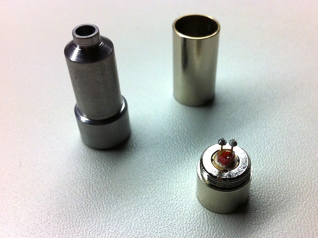
This DIY host assembly tutorial begins with the 445nm diode already pressed in an AixiZ module. For those who have never pressed a diode in a module, here are the steps. The use of an anti-static mat and wrist strap is highly recommended. In this tutorial I show the Flaminpyro diode press being used. I highly recommend this product...some use the long end of the AixiZ module turned around as a tool but this method is inferior to using the press for a number of reasons.
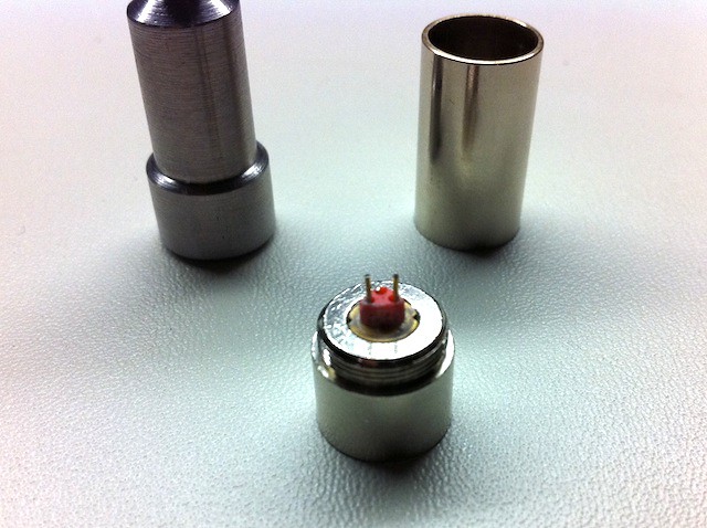
Flaminpyro diode press, 445nm diode and AixiZ module.
Place the diode in the small recess in the module with the leads up and as vertical as possible.
Screw the threaded end of the female part of the press onto the exposed threads of the AixiZ module. Make sure the diode pins are as vertical as possible.
Another option is to put the diode on top of the male part like this.
Insert the tapered end of the male part of the press into the female part. The leads from the diode must go inside the hole of the press and there should be about a 1/8" gap between the female and male portions of the press when assembled properly. Note: If this is not done correctly you could damage the pins or the diode itself during the pressing operation.
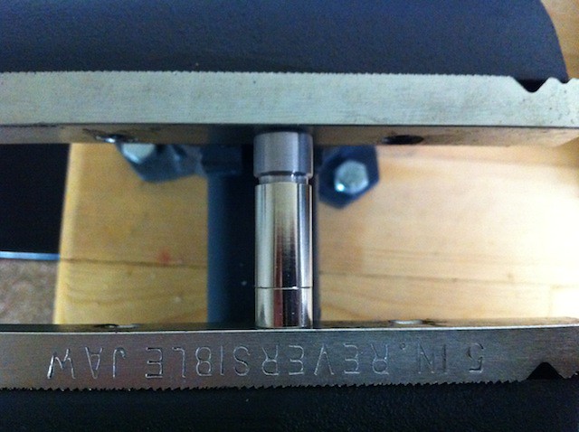
Place the assembled press in a vise, preferably one with smooth jaws. If the jaws are textured, place a rag between the vise jaws and the press ends to protect the end of the diode module.
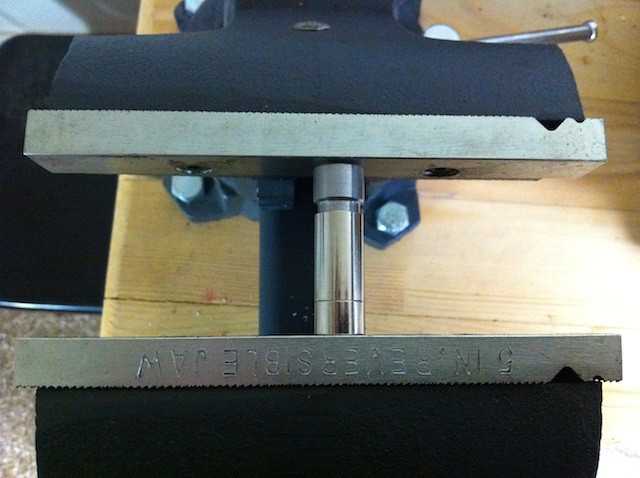
Tighten the vise until the diode is fully seated in the module. DO NOT OVERTIGHTEN. The diode should be very slightly recessed in the hole in the module when fully installed.
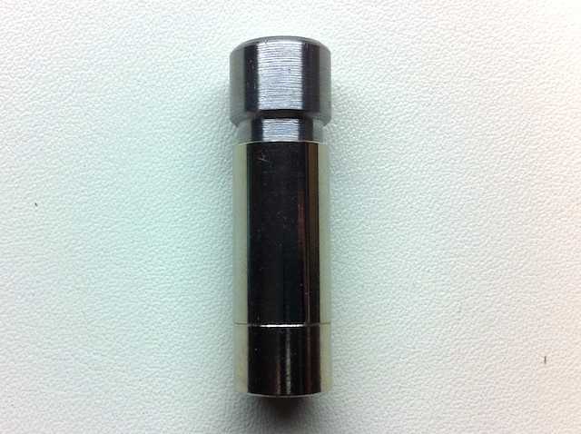
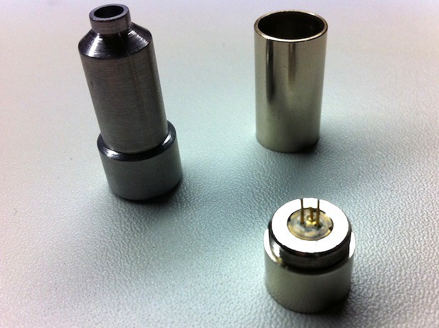
Remove the module from the press. It should look like this:
Next, I trim the little solder blobs off the diode pins with Titanium-coated scissors.
Then remove the small red plastic piece that holds the diode pins apart and you're finished!
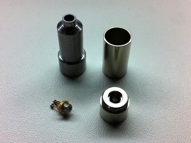
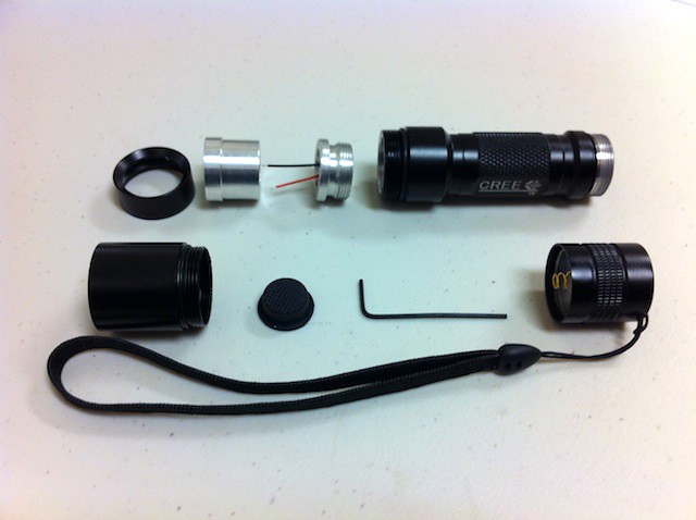
Parts included with the Survival Laser DIY assembly.
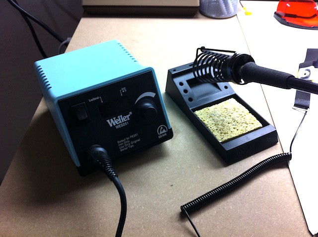
Investing in some good equipment makes assembly easier and more enjoyable. I use a Weller digital soldering station set at 675 deg F. for soldering the driver leads to the diode. Also, an anti-static mat and wrist strap.
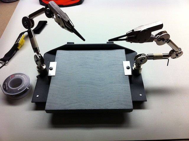
After trying some of the other cheap "helping hands" available, I found this. Makes a huge difference for me. Out of the photo is a gooseneck magnifying lens that can be positioned above the work when necessary. Here's a link to one of the lower-cost alternatives. Update: This unit looks like a better choice.
Note: To prevent the driver wires from loosening from the driver board during assembly and subsequent handling, it is recommended that you apply a small amount of GE Silicone II sealant (extremeodd also suggested hot melt glue) around the wires and in the holes where they exit the pill, and allow to solidify or cure overnight before proceeding.
Touch the two driver wires together to remove any charge that may remain in the circuit. Cut two pieces of 3/64" diameter heat shrink tubing (available from Radio Shack and many other sources) about 5/16" long and slip them over the driver leads.
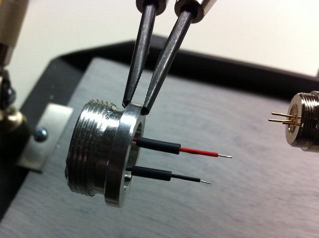
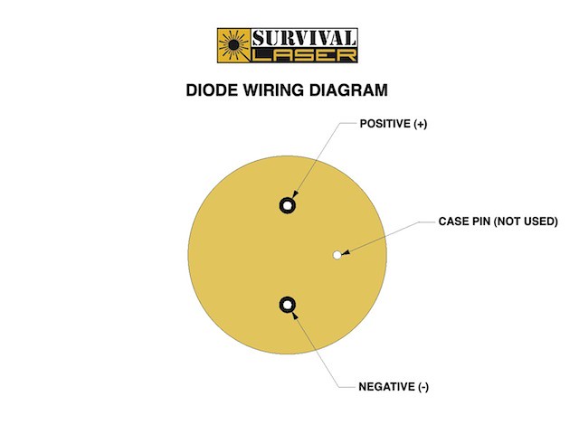
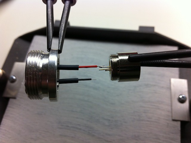
Diode wiring arrangement.
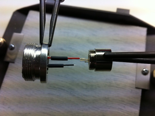
Positive lead alignment.
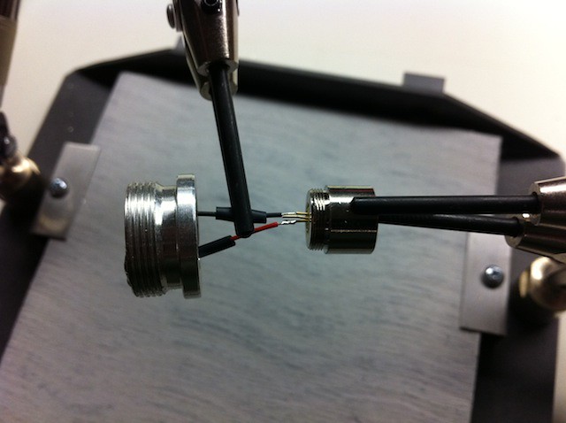
Positive lead soldered.
Negative lead alignment.
Negative lead soldered.
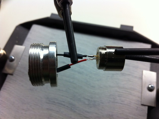
Slip the heat shrink tubing down over the soldered connections.
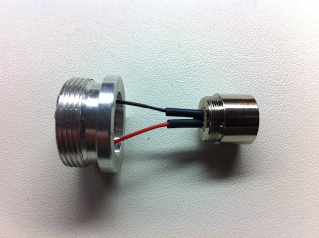
Using the tip of the soldering iron, gently brush the surfaces of the heat shrink tubes until they grip the wires and solder joints.
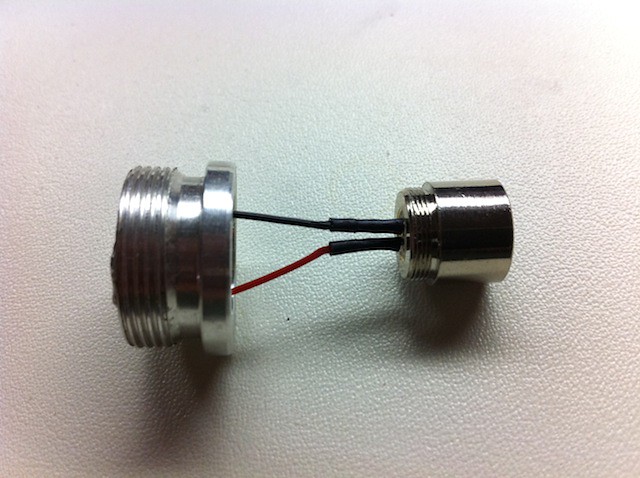
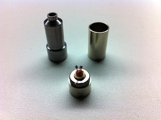
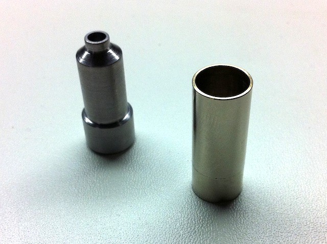
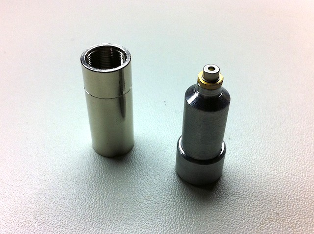
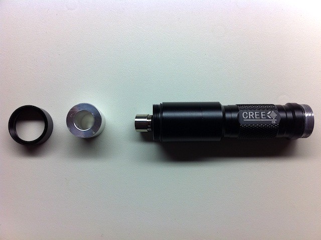
Overall parts orientation.
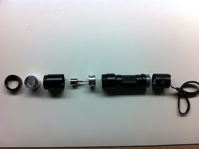
L-R: Heat sink holder, diode & driver assembly, battery holder and tailcap.
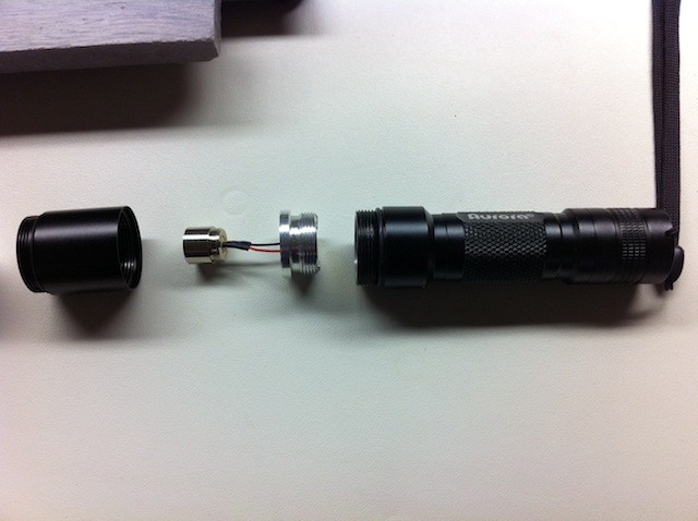
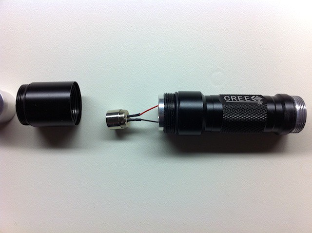
Remove the tailcap from the host battery holder. Thread the diode and driver assembly into the battery holder. Be careful not to twist or bend the driver leads excessively.
Slip the heat sink holder over the diode module and thread it onto the host battery holder. Be careful not to twist or bend the driver leads excessively.
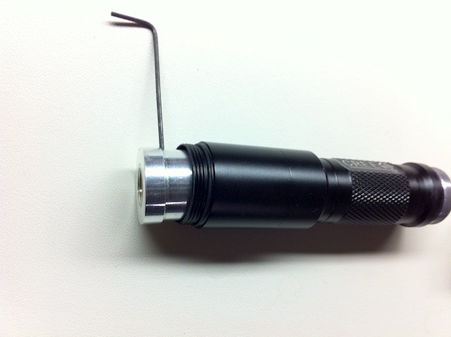
Slip the smaller diameter end of the heat sink over the diode module until the end of the module is flush with the end of the heat sink. Tighten the set screw securely.
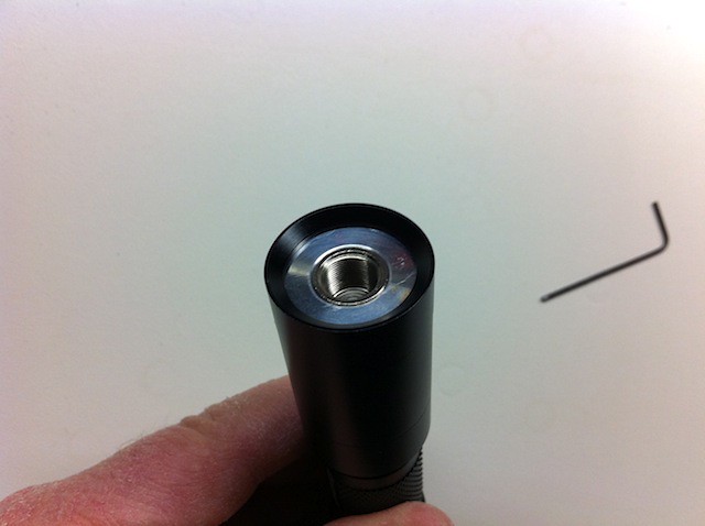
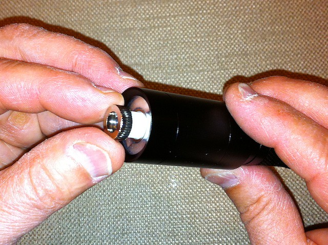
Place the bezel/retaining ring over the exposed end of the heat sink. Press the heat sink down with your finger and thread the retaining ring onto the heat sink holder until fully seated. CAUTION: Do not touch the diode inside the module with your fingers, and do not let the heat sink rotate as you tighten the bezel/retaining ring. If the heat sink rotates during tightening it could pull the wires off the diode.
For a more snug fit when installing the lens assembly into the diode module, wrap a few layers of Teflon (plumbers) tape around the exposed lens housing threads. This will help retain the focusing position, as the lens housing is a loose fit in the diode module. CAUTION: Do not allow the tape to protrude beyond the end of the lens body. Replace the tape if it begins to fray, as small loose pieces of tape near the diode window can damage the diode during operation.
Personally, I prefer the use of an external lens spring which eliminates this problem:
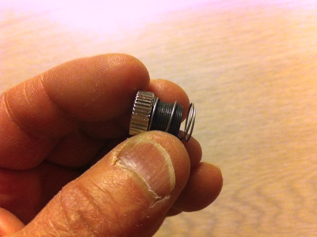
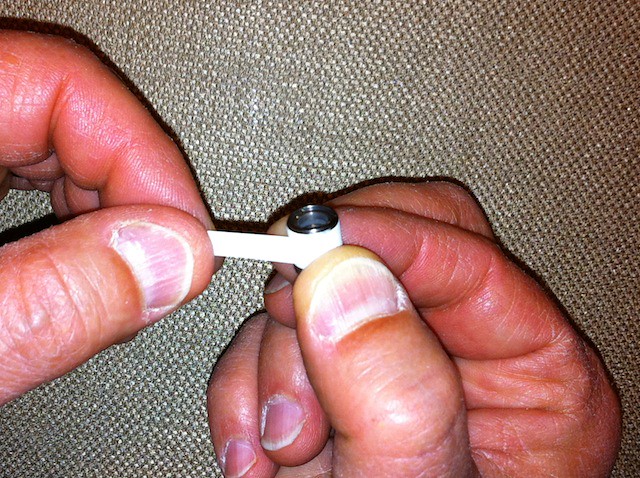
Thread the lens housing into the focusing ring with the slotted end of the lens housing facing the ring.
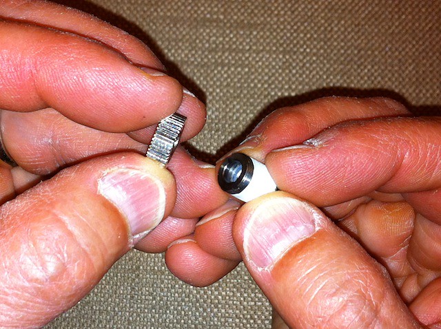
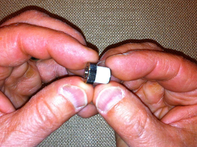
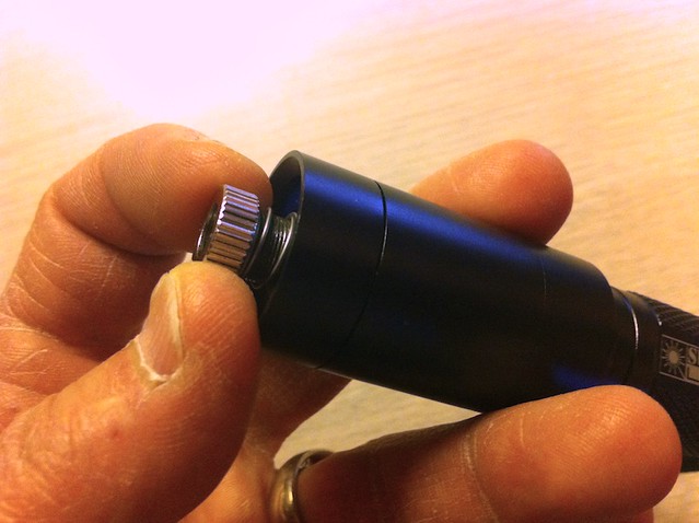
Thread the lens and focusing ring assembly into the open end of the diode module until there is about 1/8" of lens thread exposed above the module.
Lens with external lens spring threaded into the module:
WARNING: DO NOT install batteries into this build until you and anyone in the vicinity of the laser are wearing appropriate laser safety goggles! You must assume that the laser will activate upon threading on the tailcap. This build is case negative, the batteries are installed into the battery holder positive end first.
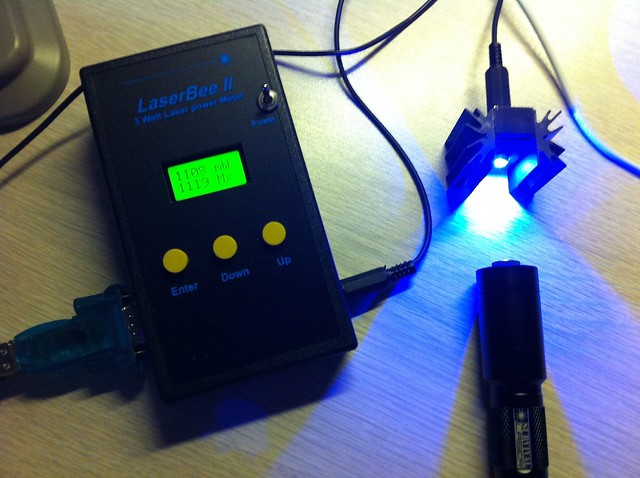
Firing it up.
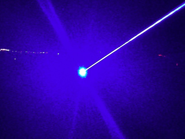
Beam shot at night in the desert southwest.
Enjoy!
Flaminpyro diode press, 445nm diode and AixiZ module.
Place the diode in the small recess in the module with the leads up and as vertical as possible.
Screw the threaded end of the female part of the press onto the exposed threads of the AixiZ module. Make sure the diode pins are as vertical as possible.
Another option is to put the diode on top of the male part like this.
Insert the tapered end of the male part of the press into the female part. The leads from the diode must go inside the hole of the press and there should be about a 1/8" gap between the female and male portions of the press when assembled properly. Note: If this is not done correctly you could damage the pins or the diode itself during the pressing operation.
Place the assembled press in a vise, preferably one with smooth jaws. If the jaws are textured, place a rag between the vise jaws and the press ends to protect the end of the diode module.
Tighten the vise until the diode is fully seated in the module. DO NOT OVERTIGHTEN. The diode should be very slightly recessed in the hole in the module when fully installed.
Remove the module from the press. It should look like this:
Next, I trim the little solder blobs off the diode pins with Titanium-coated scissors.
Then remove the small red plastic piece that holds the diode pins apart and you're finished!
Parts included with the Survival Laser DIY assembly.
Investing in some good equipment makes assembly easier and more enjoyable. I use a Weller digital soldering station set at 675 deg F. for soldering the driver leads to the diode. Also, an anti-static mat and wrist strap.
After trying some of the other cheap "helping hands" available, I found this. Makes a huge difference for me. Out of the photo is a gooseneck magnifying lens that can be positioned above the work when necessary. Here's a link to one of the lower-cost alternatives. Update: This unit looks like a better choice.
Note: To prevent the driver wires from loosening from the driver board during assembly and subsequent handling, it is recommended that you apply a small amount of GE Silicone II sealant (extremeodd also suggested hot melt glue) around the wires and in the holes where they exit the pill, and allow to solidify or cure overnight before proceeding.
Touch the two driver wires together to remove any charge that may remain in the circuit. Cut two pieces of 3/64" diameter heat shrink tubing (available from Radio Shack and many other sources) about 5/16" long and slip them over the driver leads.
Diode wiring arrangement.
Positive lead alignment.
Positive lead soldered.
Negative lead alignment.
Negative lead soldered.
Slip the heat shrink tubing down over the soldered connections.
Using the tip of the soldering iron, gently brush the surfaces of the heat shrink tubes until they grip the wires and solder joints.
Overall parts orientation.
L-R: Heat sink holder, diode & driver assembly, battery holder and tailcap.
Remove the tailcap from the host battery holder. Thread the diode and driver assembly into the battery holder. Be careful not to twist or bend the driver leads excessively.
Slip the heat sink holder over the diode module and thread it onto the host battery holder. Be careful not to twist or bend the driver leads excessively.
Slip the smaller diameter end of the heat sink over the diode module until the end of the module is flush with the end of the heat sink. Tighten the set screw securely.
Place the bezel/retaining ring over the exposed end of the heat sink. Press the heat sink down with your finger and thread the retaining ring onto the heat sink holder until fully seated. CAUTION: Do not touch the diode inside the module with your fingers, and do not let the heat sink rotate as you tighten the bezel/retaining ring. If the heat sink rotates during tightening it could pull the wires off the diode.
For a more snug fit when installing the lens assembly into the diode module, wrap a few layers of Teflon (plumbers) tape around the exposed lens housing threads. This will help retain the focusing position, as the lens housing is a loose fit in the diode module. CAUTION: Do not allow the tape to protrude beyond the end of the lens body. Replace the tape if it begins to fray, as small loose pieces of tape near the diode window can damage the diode during operation.
Personally, I prefer the use of an external lens spring which eliminates this problem:
Thread the lens housing into the focusing ring with the slotted end of the lens housing facing the ring.
Thread the lens and focusing ring assembly into the open end of the diode module until there is about 1/8" of lens thread exposed above the module.
Lens with external lens spring threaded into the module:
WARNING: DO NOT install batteries into this build until you and anyone in the vicinity of the laser are wearing appropriate laser safety goggles! You must assume that the laser will activate upon threading on the tailcap. This build is case negative, the batteries are installed into the battery holder positive end first.
Firing it up.
Beam shot at night in the desert southwest.
Enjoy!
Last edited:


") I gave this laser
I gave this laser