Welcome to Laser Pointer Forums - discuss green laser pointers, blue laser pointers, and all types of lasers

Buy Site Supporter Role (remove some ads) | LPF Donations

Links below open in new window

FrozenGate by Avery

OPEN SOURCE: The "Heavy Load" - REALLY high current (10 Amp) test load

Cool ! I even have $20 ! :) I like the black one. It's beautiful ! I'm trying to stick with your black theme with my heatsinking :)
No hurry, whenever you get the terminals figured out :)
I probably won't use them. I like watching solder drip off the board while I'm testing :crackup:


Any chance we can find black single position spring terminals on digikey? I couldn't.

Don't get me wrong, I love oshpark, and order from them constantly for drivers. But for large boards, non-purple just looks cooler :) plus, way cheaper once you're larger than 2 sq inches.
 
I wonder if aliexpress has any ?
I find all kinds of crazy stuff on there and have better luck with their quality than the bay.
I would look but I'm an Electrician not an Electronics person. I don't even know what your looking for.You have no idea how much time I spend on the simplest electronic projects. Seriously, I could wire an entire building faster.
 
Last edited:
but then we have to wait weeks on end for something as simple as a terminal to get here. Whats wrong with the spring terminal you linked to RHD, would that not work?
 
but then we have to wait weeks on end for something as simple as a terminal to get here. Whats wrong with the spring terminal you linked to RHD, would that not work?

That's very true. Something has to be available. Just finding it.
 
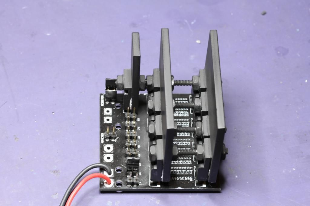
There is a moral to this story. Never let an Industrial Electrician assemble an Electronic Test Load. It ends up looking Industrial . I did stick with the black look though, I painted the heat sink with charcoal grill paint. Seemed fitting.

I'm thinking I can balance a hot dog on it. If my calculations are correct, after I set up three 4.4a drives, my hot dog will be cooked.

That's a good deal right there, I don't care who you are. Set up three drives and get a free hot dog. Multi-tasking at it's finest.

 
Haha, looks cool though. I bet you are having fun reading the chart with those screws in the way :p

Also pi, we have screw terminals like those picked out for the driver input, we are just looking for something spring loaded to hold multimeter probes.
 
Last edited:
Haha, looks cool though. I bet you are having fun reading the chart with those screws in the way :p

Also pi, we have screw terminals like those picked out for the driver input, we are just looking for something spring loaded to hold multimeter probes.

Thanks :beer: I think it turned out OK. Pretty much the way I wanted it :) Pretty much any heat sink that's on the front row of diodes is going to make the chart hard to read, unless you bend the front row of diodes forward. Then they start getting in the way of the jumpers.
Honestly. I will probably never look at the chart. I'm a guy, we don't read directions until something blows up :)

It's really rigid like this and has some heft to it. Now I have to dye some perfboard black to mount it on. I'm going to mount it on a board with stand offs along with a voltmeter , ammeter, two cell battery holder, switches and a heat sink to put drives on.
I'll have a little self-contained drive set-up station. No more test leads all over the place :)
 
Hey, thats a good idea. I may do something like that eventually. Maybe if I can get a piece of scrap aluminum angled plate from a nearby metalworking shop.

So, have you decided on terminals, RHD? What you linked to should be fine, shouldnt they?
 
Hey, thats a good idea. I may do something like that eventually. Maybe if I can get a piece of scrap aluminum angled plate from a nearby metalworking shop.

So, have you decided on terminals, RHD? What you linked to should be fine, shouldnt they?

Anyone find black ones? I'd really like black ones....

Re: the chart - I actually use it constantly. If you want an accurate VDrop, it's tough (EDIT: okay, maybe not "tough", but annoying and unnecessary) to do it in your head, and these diodes were picked specifically for their VDrops. It's not a simple constant drop either. The chart is scaled for current and diode count. It's useful.
 
Last edited:
Hey, thats a good idea. I may do something like that eventually. Maybe if I can get a piece of scrap aluminum angled plate from a nearby metalworking shop.

So, have you decided on terminals, RHD? What you linked to should be fine, shouldnt they?

That's what I'm using for the base of it, a piece of aluminum. The perfboard will be on standoffs bolted to the piece of aluminum. That will leave me a gap to keep the wiring all hidden. :beer:
 
Anyone find black ones? I'd really like black ones....

Re: the chart - I actually use it constantly. If you want an accurate VDrop, it's tough (EDIT: okay, maybe not "tough", but annoying and unnecessary) to do it in your head, and these diodes were picked specifically for their VDrops. It's not a simple constant drop either. The chart is scaled for current and diode count. It's useful.

I never said it wasn't useful. Just that I probably won't use it :) I could be wrong, I might find it very useful. I will find out tomorrow when I start using it . :beer:

I probably don't use the same methods to set up drives as people with more experience and knowledge. I taught myself and that's the only way I know. Many an innocent diode was sacrificed in the process.

To be fair, I don't either. I never use adjustable drivers in fact.

I basically use the test load to test new fixed driver designs. That's about it.
 
To be fair, I don't either. I never use adjustable drivers in fact.

I basically use the test load to test new fixed driver designs. That's about it.

I'm wanting to get away from adjustable drives myself. My goal is to be able someday to build my own drive for a certain diode at a certain current for a certain build.
I've been playing around with drive design software, I find it curious that when I change current values for a drive, components/values start changing besides just the set resistor :thinking:


Back
Top