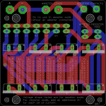
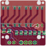
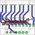
Alrighty everyone. This was quite a while ago, but I am FINALLY ready to get some of these made. With help from DjQuan, I got the input and test pads changed a bit to fit these parst:
screw terminal lever terminal. I will probably use screw for the input, and then get a few lever terminals and see if they fit DMM probes. If they don't I will use just header pins and use alligator clip probes.
I am using SeeedStudio like RHD did, simply because they are quite cheap. I am thinking of going with white since its a bit cheaper and I think it would the black/white contrast would look really nice. Anyone else interested in these? I would be happy to get rid of most of them, might ask a few $ to cover shipping and part of the PCB cost. We could also order 10x or 5x (depending on interest which determines how many boards I get) sets of parts to drive the cost down a bit on them.
part list:
-terminal 1:
lever(optional)
-terminal 2:
screw(optional)
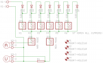
-diode (x7):
FFPF10UA60ST
-resistor (x1):
.1 Ohm. As RHD stated in post #4:
Even though the board itself suggests using a 1 ohm resistor, I would strongly suggest moving to a 0.1 ohm resistor instead. It doesn't really make the conversion hard (just move a decimal place in your head), and it saves you from dropping 4V over the resistor when you're testing 4A, etc. That's a lot of voltage drop.
-headers (x9):
3M9447-ND
jumper:
this or
that. Doesn't matter which, but you need 2 of them. These seem a bit ridiculous, because its either 30cents from Digikey, or get them for pennies a piece, but wait on the slow boat/rickshaw from china. Personally, I would rather pay the 30cents and get it here in less than a month.
Here is a shared digikey cart with everything in it (not all is necessary):
http://www.digikey.com/short/7hq59c
so what I need to know from people:
1) number of people interested in how many boards
2) is the PCB color OK (white vs. RHD's black)
3) do people want me to order all the parts so we can get a discount on them
edit: just to clarify, this is the board from post #4 of this thread, not DjQUAN's board.


")