Welcome to Laser Pointer Forums - discuss green laser pointers, blue laser pointers, and all types of lasers

LPF Donation via Stripe | LPF Donation - Other Methods

Links below open in new window

ArcticMyst Security by Avery

Nichia NUBM34T 115W 455nm

Joined
Feb 25, 2010
Messages
1,643
Points
113
Hmmmm....Well I really find Styro's video's....er....ah....entertaining.....However...They disturb me....and it is sobering to imagine if someone duplicates the Stryo experiment....Well...." It is like Lasing a Stick of Dynamite "....in the hands of someone with no appreciation of the power they control.
Yes...He does issue many, many disclaimers and warnings....HE SHOULD !!!! Are we on the Threshold of " DEW for Dummies" ?????? :eek::eek::eek::eek::eek::eek::eek: CDBeam


Joined
Jul 10, 2015
Messages
9,903
Points
113
I would like to have seen Drake use a big homemade BE on his 31 array with the factory gang lens intact just to see how well it grouped at 5 and 10 meters but it's probably better that he kept his display up close in his YT video.

That said I love the look of multiple beams and know I could build a ring of articulated heads ( laser in heat sink ) each on a small bar with a tilt/run-out adj. screw and set them up them each by adjusting ( x axis ) so they follow the center line as adjusted ( y axis ) to converge along the center line by following a cone shaped adjuster run down a center threaded rod with a spring pushing against it, each would have a cam like follower that rides on the cone, turn the nut and as the cone is forced down the threaded rod against the spring all the beams converge ( y axis ) along the center line until reaching the desired distance........but this is not for the array in this thread.
 
Last edited:

tedcs

0
Joined
Jul 27, 2012
Messages
48
Points
18
Hmmmm....Well I really find Styro's video's....er....ah....entertaining.....However...They disturb me....and it is sobering to imagine if someone duplicates the Stryo experiment....Well...." It is like Lasing a Stick of Dynamite "....in the hands of someone with no appreciation of the power they control.
Yes...He does issue many, many disclaimers and warnings....HE SHOULD !!!! Are we on the Threshold of " DEW for Dummies" ?????? :eek::eek::eek::eek::eek::eek::eek: CDBeam
I understand the concern, but the many warnings should be sufficient for anyone not aspiring to a Darwin Award.
" If you try this at home, you will probably die " is really easy to understand. Your point is taken, in any case.
Not to worry, lasing a Stick of Dynamite would not cause it to explode, unless it is confined. Otherwise, it may be disposed of by burning. I have burned nitroglycerine myself; it burns fast and quietly. I would not try it with a pulse laser, however. (Today, I would not do anything whatsoever.)
 

tedcs

0
Joined
Jul 27, 2012
Messages
48
Points
18
I would like to have seen Drake use a big homemade BE on his 31 array with the factory gang lens intact just to see how well it grouped at 5 and 10 meters but it's probably better that he kept his display up close in his YT video.
I have been thinking that beam expansion or expanding expanded beams would be interesting/instructive.
Too, it is best to avoid implying or demonstrating capabilities which might be considered not constructive or politically incorrect.


said:
That said I love the look of multiple beams and know I could build a ring of articulated heads ( laser in heat sink ) each on a small bar with a tilt/run-out adj. screw and set them up them each by adjusting ( x axis ) so they follow the center line as adjusted ( y axis ) to converge along the center line by following a cone shaped adjuster run down a center threaded rod with a spring pushing against it, each would have a cam like follower that rides on the cone, turn the nut and as the cone is forced down the threaded rod against the spring all the beams converge ( y axis ) along the center line until reaching the desired distance........but this is not for the array in this thread.
I get the idea although I can't quite visualize the mechanism as described. That's OK, I would suggest thinking in terms of the articulated heads' motion capability, first. How would the lasers move if you had a magic wand? I would be great if they each had 6 degrees of freedom, yes? While that may not be very practical. I consider it a useful exercise. Then decide whether the mechanism, as envisioned or modified, can do the job. Whether one would like to build one, or 20,000 will affect the approach, somewhat. :)
 
Last edited:
Joined
Feb 25, 2010
Messages
1,643
Points
113
Hmmmmm... ??????? " Lasslo Buddy" ...." Ice is Nice ".....DEW for Dummies !!! ( D4D ).....YIKES !!!.....I will NOT be posting further specifications for the GPP ( General Prison Population ) !!!
CDBeam
 
Last edited:
Joined
Jul 10, 2015
Messages
9,903
Points
113
Not to worry, lasing a Stick of Dynamite would not cause it to explode, unless it is confined. Otherwise, it may be disposed of by burning. I have burned nitroglycerine myself; it burns fast and quietly. I would not try it with a pulse laser, however.

You mispoke or are thinking about low order explosives such as black powder which need to be confined although 4F will explode under it's own weight in a large enough container when ignited, even an open top 5 pound coffee can of 4F will produce a palpable shock wave but BP is on the top end of low order, now high order such as TNT needs a concussive force to initiate such as a blasting cap and will detonate unconfined but if lit with a match will safely burn.
 

tedcs

0
Joined
Jul 27, 2012
Messages
48
Points
18
You mispoke or are thinking about low order explosives such as black powder which need to be confined although 4F will explode under it's own weight in a large enough container when ignited, even an open top 5 pound coffee can of 4F will produce a palpable shock wave but BP is on the top end of low order, now high order such as TNT needs a concussive force to initiate such as a blasting cap and will detonate unconfined but if lit with a match will safely burn.
OFF TOPIC WARNING
Certainly, you are correct with respect to black powder and TNT, also.
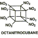
The material in question was "a Stick of Dynamite," however. Dynamite is a formulation, the most basic type is sawdust and nitroglycerine. Tri-Nitro Toluene is a different chemical. Dynamite does not contain any TNT, which is more powerful then nitroglycerine. There is also the category of very high explosives which includes C-4 (Cyclo Trimethylene Trinitramine), PETN (Pentaerythritol Tetranitrate), and one of my favorites, China Lake-20 (Hexanitrohexaazaisowurtzitane) (If I had any sense at all I would not have written this.) 😳
As I explained to some folks at NASA & Lockheed/Martin: One who knows how to blow things up may know a thing or two about how to make things which will NOT blow up. It is not necessarily true, but it worked for me.
I remember how excited I was when, in third grade, I found out how to make black powder, reading an encyclopedia. This was slightly before lasers were invented. 😇
Extra Credit:
octanitrocubane.png
 
Joined
Feb 25, 2010
Messages
1,643
Points
113
Hey....You's guys ....The Term " It's like Lasing a stick of Dynamite " is a quote from the movie.....Real Genius.....It was the " Ah Ha" statement made by Chris Knight when he was explaining to his buddies about his concept for the 6 Megawatt Laser !!! Sheeezzzz....Although....It has been entertaining to watch you go off on a tangent.......Obviously....I am easily amused !!!
Perhaps....I will not be so awfully obtuse. next time ????????....NNnnnaaaaagh !!! Why change now !!! CDBeam
 
Joined
Jul 10, 2015
Messages
9,903
Points
113
If you built your own controller I wonder how well you could converge and even reshape the 24 beams from a nubm34 using a DLP ?

Probably not all that well at distance but as a 1st step to collimate before a big beam expander maybe........
 
Last edited:

tedcs

0
Joined
Jul 27, 2012
Messages
48
Points
18
Re: Nichia NUBM34 115W 455nm
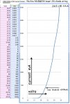
Voltage vs current graph:


This is rather elementary, but so am I.
I have to extra careful to avoid blowing stuff up; direct current only.
Having no current / voltage graph for the NUBM34, I decided to make one.
A couple of areas have wiggly artifacts, due to necessary wiring and heatsink changes.
As such, I do not warrant perfect accuracy but it is probably good enough to give an idea what to expect.
I only tested 1/4 of the device, one row, so that it would not get too dam hot. 👺
As it was, 86 watts was delivered by the power supply, operating in the vicinity of rated output, for one row of diodes.
With all rows operating, the NUBM34 will generate on the order of 250 Watts of heat. It's maximum allowable temperature is 75º celsius.
A 2" x 2" heatsink would be insufficient, in the extreme.
Preparing to connect the NUBM34 to the power supply, I first set the supply to 17 volts, current limit 50mA.
Turning on the power supply and setting the voltage and current before connecting the laser helps avoid damaging stuff.
When connected, the diodes will light, the intensity will be safe and far below lasing, which requires about 430 mA.
The voltages you find may be different, but pretty close.
p.s. As is probably obvious, this device can be wired for 25v, 50v, or 100v power supply.
- - - The supply MUST have current limiting capability in any case.
Be careful, avoid incinerating anything unintentionally.
NUBM34 V I graph.jpg
 
Last edited:
Joined
Feb 12, 2016
Messages
589
Points
63
Hi tedcs,

You said that lasing starts at 430mA? This looks like with nubm08/44.
Strange that with china made Osram chip I found that 200mA was enough to reach the lasing threshold. Maybe chinese make a different dye, not one the japanese do???

BTW one guy from my organic chemistry course did a postdoc with Eaton about nitrocubanes in late nineties. And it was veeery expensive chemistry...

Back to NUBM34. Did you check the spot with gang lens before cutting it away? Haw parallel the beams were?

Did you have time to check what I have asked in the post 31: "the distances where the beams (or better beam spots on your thermal paper because not all of the beam outer part is of value) start to touch each other like on your picture in post 5. In both horizontal and vertical dimentions." ?

Thank you.
 
Last edited:

tedcs

0
Joined
Jul 27, 2012
Messages
48
Points
18
You said that lasing starts at 430mA? This looks like with nubm08/44.
Strange that with china made Osram chip I found that 200mA was enough to reach the lasing threshold.
Maybe chinese make a different dye, not one the japanese do???

I should have qualified that number.
My recollection is that the NUBM31 spec is 220 to 420 mA, I do not know whether this is relevant.
I found that the lasing threshold varied. 430 mA is the current at which all the diodes in the row were lasing.
I guess I had better measure the turn on current with all 24 of the diodes connected, instead of 6.
I wonder if diode characteristics change as they age. The device is almost certainly used, I know not how long.
The serial number is 420 which seems a very low number.

BTW one guy from my organic chemistry course did a postdoc with Eaton about nitrocubanes in late nineties.
And it was veeery expensive chemistry...


In a different life, I visited some companies which were doing propellant chemistry research. I remember that it was very expensive and dangerous. It is just as well that I have no direct experience with oxetanes, cubanes, and especially fluoronitramines, which could blow up if you looked at them, even at very low temperatures. 😲

Back to NUBM34. Did you check the spot with gang lens before cutting it away? Haw parallel the beams were?
Did you have time to check what I have asked in the post 31: "the distances where the beams (or better beam spots on your thermal paper because not all of the beam outer part is of value) start to touch each other like on your picture in post 5. In both horizontal and vertical dimentions." ?
Thank you.
I have been considering the best way to do these, but have not yet done them.
My familiarity with the device is improved and it's mostly a matter of fixturing.
I'll see what I can manage today, perhaps.
Now the bad news: I dropped the device a couple of weeks ago and one row of the matrix lens was broken off. I had only made a print of the beams directly on the surface of the lens at that time. (bummer) At this point, I decided to remove the remaining intact lens rows, get photos of the 'bare' diodes, and grind off the sharp edges with a diamond disc. I plan to stick the lens back on and make more images before too long. Some fiddling will be necessary as I have no micopositioning devices. C'est la dreck. <whimper>IMG_0701.JPG
IMG_0676.JPG
 
Last edited:

tedcs

0
Joined
Jul 27, 2012
Messages
48
Points
18
An update on NUBM34 lasing thresholds:
NUBM34 diodes lasing neg.jpg
The diode lasing current thresholds were tested, one row at a time, to minimize heating. (and mistakes)
For heat sinking purposes, the module is clamped to a 14 pound aluminum block.
For each row, current was increased until lasing was observed, the number of lasing diodes was recorded.
The voltage across the row of diodes was between 20.12V and 20.24V when all six diodes were lasing.
As such, each row of diodes lasing at minimum current, draws nearly 8 watts, or 32 watts with all 4 rows lasing.
See below, three diodes lasing, and three below the lasing threshold. Without a HUGE heatsink the NUBM34 can
heat up quite quickly causing electrical characteristics to change, depending on the actual power applied.
With all 24 diodes connected, and operating at maximum current the rated optical power output is 115 Watts.
The heat dissipation may be estimated at 230 Watts, at least.
Ambient Temp here: 24.5º C
I don't have a laser calorimeter, yet.
The front of the NUBM34 was covered with a piece of tissue paper to reduce the extreme intensity and glare.


IMG_0715A.jpg
 
Last edited:

tedcs

0
Joined
Jul 27, 2012
Messages
48
Points
18
Hi tedcs,
You said that lasing starts at 430mA? This looks like with nubm08/44.[...]

Well, here's the deal, when I was checking the threshold current the first time, I was using a smaller heatsink than a big block of aluminum.
As the device gets hotter, the current (voltage) required for lasing increases. Each diode has it own idea about what the threshold is. A row of six diodes may each be lasing at say 20.16V & 380mA and suddenly three of them go completely dark. Turning up the voltage a little will cause them to turn on, but this is not seem like a good idea and almost certainly is not proper behavior. Perhaps the NUBM34 is rather more used than I anticipated. I decided to report a current threshold of 420mA as I felt sure that all diodes would be lasing at this point. In any case, the numbers in the post #61, above are better, maybe, a little bit, I hope.


said:
BTW one guy from my organic chemistry course did a postdoc with Eaton about nitrocubanes in late nineties. And it was veeery expensive chemistry...

I recall that the angle of the vertex bonds in cubane really do not like to be at 90º and are highly strained. It is probably necessary to fly the atoms through a black hole in order to get them to stick together in that arrangement.

"[COLOR=rgb(204 said:
Did you have time to check what I have asked in the post 31: "the distances where the beams (or better beam spots on your thermal paper because not all of the beam outer part is of value) start to touch each other like on your picture in post 5. In both horizontal and vertical dimensions." ?
Thank you.

I glued the gang lens back on the NUBM34. The alignment is not perfect, but it seemed good enough for the moment. I decided that it probably is not possible for me to get it right without adjusting it with the lasers operating. I will to do it over.
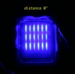
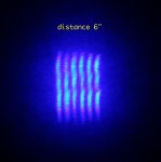
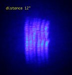
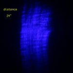
I fiddled and puzzled with setups hoping to get decent images of beam spots at distances. Projecting the beams along a sheet of paper did not show anything useful. I decided that projecting the beams onto a sheet of paper and photographing it from the other side was probably the only way I could get anything even marginally helpful. I attach four images created this way with the paper normal to the beams at four distances: 0", 6", 12" and 24" Frankly, they are awful! I wonder how the device for which the NUBM34 is made uses the beams and what it's optical path looks like. I expect that the lousy images I made are mostly a result of the gangs lens being slightly off. The set up I'm using suffers from an excess of chewing gum, bailing wire, duct tape, and hair balls. If you have any suggestions as to how to approach this in a less inept fashion, I'd be like to hear it. Clues are in short supply here.
At this point, in the longer term, I'm leaning toward leaving the gang lens off and attempting to throw together a larger diameter beam-forming/collimator assembly. I notice that there are several ways to approach this, involving single axis lenses, prisms, condensers, expanders, knife-edges, aspherics, anamorphics, ad nauseum. Now, if I only had some practical experience... I feel kind of like the first time I was assigned a small program to write in Fortran. What would be trivial now, seemed impenetrable at the time.
IMG_0719.JPGIMG_0720.JPGIMG_0721.JPGIMG_0722.JPG


Top