Welcome to Laser Pointer Forums - discuss green laser pointers, blue laser pointers, and all types of lasers

Buy Site Supporter Role (remove some ads) | LPF Donations

Links below open in new window

FrozenGate by Avery

Nichia NUBM34T 115W 455nm

I ran the nubm31t all 4 channels parallel at 9.412A for about a minute

CH1: 2.386A
CH2: 2.328A
CH3: 2.436A
CH4: 2.306A

I was thinking of putting a ~ 4A fuse on each channel. Once one blows, the rest will blow immediately.

During testing of the nubm31t, I killed a laser driver which caused around 8.5A to be split between two channels. This unexpected event made me realize the diode should have no problems at 4A when the fuse reaches that point.

I will be running this set up for the time being until something occurs. I had no luck finding a proper high voltage driver that matches the nubm31t. It also needs to be reasonably sized and portable.

The driver I am using is the Maiman SF6060, 95% efficiency stepping from 52V down to 22V @ 10A. So much better than the other driver I had which did have 3 channels, but just utterly failed past 3A on any channel. It also produced so much heat, but I was not able to measure the efficiency.

____

If I were to use a 1ohm resistor across each channel and each channel running at 3A, how much losses would I be getting?


I ran the nubm31t all 4 channels parallel at 9.412A for about a minute
[...]
If I were to use a 1ohm resistor across each channel and each channel running at 3A, how much losses would I be getting?

A fuse needs to be in series with each channel, like the resistors.

3A through 1Ω would give a 3V drop across the resistor. A x Ω = V
3A current through a 3 volt drop is 9 watts. V x A = watts
Current ( A = amps ) may be shown as I i.e. V x I = watts ( I don't remember why)
Also, A^2 / Ω = watts

A 0.1 Ω ohm resistor would drop 0.3V

3A current through a 0.3 volt drop is 0,9 watts.
 
Last edited:
Also, A^2 / Ω = watts

"I" is current in amperes (originally for intensity, maybe? Don't remember), not "A".

Also, "R", not Ω

Structure itself is wrong as well. Power is resistance squared multiplied by the current:
P=I²R

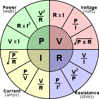
If you're having trouble, these cheat sheets are common. It's easier than it looks, as they're just algebraic reordering of the same thing:

ohms-law-formula-wheel.png


I was thinking of putting a ~ 4A fuse on each channel. Once one blows, the rest will blow immediately.

That's not how fuses work. In your example, 12A divided among 4 channels is 3A. If one pops, 12A divided by 3 channels is 4A. All fuses remain intact. Even if you used a 3A fuse... It depends on the device selected, but a 3A fuse will run at 4A for several minutes or perhaps indefinitely. Google fuse trip curve for examples.
 
"I" is current in amperes (originally for intensity, maybe? Don't remember), not "A".
Also, "R", not Ω
Structure itself is wrong as well. Power is resistance squared multiplied by the current: P=I²R
If you're having trouble, these cheat sheets are common.
It's easier than it looks, as they're just algebraic reordering of the same thing:
Screen Shot 2020-05-25 at 2.52.59 PM.png
Sigh, I always have trouble. ;) Yes I≠A, R≠Ω, E≠V
I knew this stuff 60 years ago, but don't use it often enough and my braincell had a parity error.
Back then, we had to use "O" and "I" because 0.png and 1.png had not been invented, yet.

said:
That's not how fuses work. In your example, 12A divided among 4 channels is 3A. If one pops, 12A divided by 3 channels is 4A. All fuses remain intact. Even if you used a 3A fuse... It depends on the device selected, but a 3A fuse will run at 4A for several minutes or perhaps indefinitely. Google fuse trip curve for examples.
Agreed, although there are fuses that are extra fast, it would be more safe to use four supplies with current limit. Amazon has small modules for less than $5 each, which might do the job. ( up to 36V in, up to 5A out)
 
Last edited:
Why this trouble with fuses?

Buy a decent CC driver, connect all rows in series et voila!

Yes, it does not make sense to attach gang lens back after it was taken off. All spots are awful indeed. Can you do a picture of spots without gang lens on a dark glass?
This is how I made the picture when I knife edged 4 NUBM44 diodes - using dark glass of a rectangular bottle with flax oil as screen gave good result to me. I could take this picture without safety googles before camera and you can see minor gaps between beams well enough...
The current was 0.5A.

KE2a.jpg
 
Thanks for the explanations.
Looking at the fuse current/time charts are pretty interesting.


I read and was told we need laser specific drivers for diodes because they are more sensitive than LEDs. If DC boost drivers can be used, this will make things much easier for me!


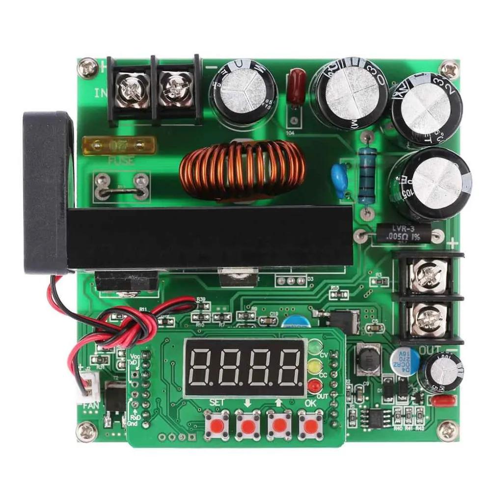
Is something like this suitable? They will not have any voltage spikes? If they fail during operation, will they damage the array?

Has anyone found a more reliable 100VDC+ boost converter? These $30 are using the bare minimum components.
 
Yes, a specifically protected driver is needed for laser diodes but to my IMHO understanding of the current situation those drivers ony exist for single diodes and do not output high voltages when I want to combine several diodes in series.

Second point - if any voltage spike happens in a series of 5-6 diodes, then each diode will take only a part of it (voltage excess divided by number of diodes) and if 20-24 are in series the spike portion on each diode would be even less.

Third point - all arrays from nubm05 to nubm3x have a kind of protection device or ESD protection diode built in (this is written in spec sheets).

Fourth point - these 50-100W lasers arrays of today, are they really weaker than LEDs? I doubt. Maybe they were sensitive at the very dawn of the laser era...

That is why I use these DC boosters since 2017 for every set up with 4 or more diodes and did not have any trouble with them yet. But I also do not play with lasers every hour, just once a week or two. So I do not expect 50.000 working hours from any of my devices.
 
Why this trouble with fuses?
Buy a decent CC driver, connect all rows in series et voila!
That makes sense to me as well.
I am inclined to use modules rated for well above the current required.
Some suppliers exaggerate their capacity.


Yes, it does not make sense to attach gang lens back after it was taken off. All spots are awful indeed.
Can you do a picture of spots without gang lens on a dark glass?
OK!! I have to take the gang lens off, in any case.
I don't know if I have a suitable dark glass bottle, but should be able to find something. I have an arc welding filter which should work if it is not too dark. I don't have flax/linseed oil, but may have a suitable substitute: Europium/Strontium Aluminate powder.
I've been wondering what to do with it.
Update: Number 10 welding filter is much too dark. Plain white paper is OK however.


This is how I made the picture when I knife edged 4 NUBM44 diodes - using dark glass of a rectangular bottle with flax oil as screen gave good result to me. I could take this picture without safety googles before camera and you can see minor gaps between beams well enough...
The current was 0.5A.
dark bottle flax oil.png
Excellent! This image is extremely helpful.
It gives me a much better idea what the goal is, in addition to a better way to image beams.
<insert an hour>

I have much better images - coming soon
 
Last edited:
Yes, a specifically protected driver is needed for laser diodes but to my IMHO understanding of the current situation those drivers ony exist for single diodes and do not output high voltages when I want to combine several diodes in series.
I say NO to the specifically protected driver requirement, it is not so. I too, have never seen a higher voltage laser diode specific driver.
Actually, I have never used a laser diode driver. There are options which are less idiot-proof but are much more flexible.
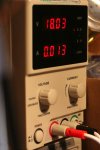
A plain bench power supply works for me. If one is not careful, it is easy to set voltage or current to high and ... oh, s---t!
IMG_0723s.jpg


Second point - if any voltage spike happens in a series of 5-6 diodes, then each diode will take only a part of it (voltage excess divided by number of diodes) and if 20-24 are in series the spike portion on each diode would be even less.
That sounds correct.
Third point - all arrays from nubm05 to nubm3x have a kind of protection device or ESD protection diode built in (this is written in spec sheets).
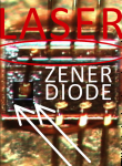
They do have a protection diode on each laser diode:
The laser diode is the horizontal bar within the red ellipse,
the zener diode is the black cube, it is in parallel with the diode.

LASER DIODE.png

Fourth point - these 50-100W lasers arrays of today, are they really weaker than LEDs? I doubt. Maybe they were sensitive at the very dawn of the laser era...

That is why I use these DC boosters since 2017 for every set up with 4 or more diodes and did not have any trouble with them yet. But I also do not play with lasers every hour, just once a week or two. So I do not expect 50.000 working hours from any of my devices.

My guess is that since lasers require much higher precision than an LED, they are probably more fragile in every respect. Laser diodes have been around for a while, though and they are likely to be more robust that they used to be. Adding a zener diode directly to laser diodes should help quite a lot.

I won't comment on the expected lifetimes of laser diodes in my possession. I used to have a number screwdrivers with chunks missing from the blade appearing as if they had sustained very high current arcs.
 
Last edited:
Searching for a clue, I wanted to see the beam shape of an uncollimated laser.
A blue 7 Watt NUBM44 was on hand.
A piece of white paper was put in the beam path about an inch from the front of the 12mm diode mount.

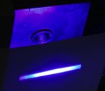
laser no lens.jpg
The beam was less unattractive than I had expected, but the ends are truncated by the diode mount.
While this is not an issue when a collimator is place, I still want to be able to see the full extent of the beam, without the collimator.
I'll deal with that later.

I also want to see the effect of a lens or two:
IMG_0773 c.jpg(thumbnail)
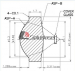
This is a Ø29mm, FL 15mm, positive meniscus lens! (or so I was told)
It focuses down to a spot with wings, about 8 inches out.
While it is not too bad for a shot in the dark, I don't know how much light is going elsewhere.
A laser power meter would be nice, but I don't have such a thing yet.
The laser is operating at about 0.4 Amps


IMG_0762 c.jpg(thumbnail)

The power was, briefly, set to 3.7 Amps at 4.8 Volts. (full power)
This resulted in a hole in the paper about 1mm in diameter. ( .04")

IMG_0775 s.jpg(thumbnail)
The block of stainless steel behind the paper was unaffected.
 
Last edited:
Looks like there's a smaller 74W rated block of 14 emitters but what's interesting is that makes these just over 5.25w each which is a jump up from the 4.75w rated diodes that we overdrive to 7w..........too bad we can't use them individually.

 
Looks like there's a smaller 74W rated block of 14 emitters but what's interesting is that makes these just over 5.25w each which is a jump up from the 4.75w rated diodes that we overdrive to 7w..........too bad we can't use them individually.
Well, that is right interesting. Two rows of diodes is easier to deal with than four.
Of course, the question still remains – what are we gonna do with it. We'll burn that bridge when I get to it, I guess.
By the way, while we cant use matrix lasers individually, I don't know that it will always be the case.
I'm not going to pursue it right away, but it could happen.
Could the top of a laser array be cut off just above the feed-throughs? Of course
Could the base plate be hacked in to pieces also? Of course
One could, then rearrange the individual diodes and stick them together in a big blob.
Cooling can be handled.
What everyone probably considers a show stopper is that the blue diodes turn to
shit in the air.
It's ok, we can stick the diode conglomeration in an empty olive jar, pump out all the air, and fill it dry nitrogen.
Or do something else with them. The only thing that could prevent this is if none of us can be bothered to do it.
No problemo. Have you seen videos of folks who make vacuum tubes at home, for fun?
I can roll it around in my braincell, in any case.
IMG_0601 Chop3.jpg
 
Pretty sure you're going want to use an aspheric lens to alleviate those awful wings.
Something like the G2 style mayhaps.
1591458184602.png
 
Last edited:
Hi tedcs,

Did you have the chance to mesure what I have asked before? I mean distances f3 (in horizontal and vertical dimension) at my hand made picture in post 23 of this thread?
 
Hello, someone is helping me. I bought these from the picture and I want to mount them but I don't know
 

Attachments

  • Screenshot 2020-09-14 005533.jpg
    Screenshot 2020-09-14 005533.jpg
    123.3 KB · Views: 25
  • Screenshot 2020-09-14 005630.jpg
    Screenshot 2020-09-14 005630.jpg
    119.5 KB · Views: 25
Do you have laser safety glasses ?
You will need laser safety glasses that attenuate 445-455nm or what ever wavelength you are working with to keep from permanently blinding yourself.

The array will need to be mounted to a heat sink, make sure to use thermal compound or indium foil or you will burn it out quickly.
I used thermal compound between my array and my heat sink which worked just fine.
Make sure you observe the polarity when connecting your driver, that driver outputs 85V DC meant to drive all the lasers in series so you will connect your 4 strings in series.

Most of all use caution and practice laser safety at all times, sorry to harp on that but it's important.
 
Last edited:


Back
Top