Welcome to Laser Pointer Forums - discuss green laser pointers, blue laser pointers, and all types of lasers

LPF Donation via Stripe | LPF Donation - Other Methods

Links below open in new window

ArcticMyst Security by Avery

Nichia NUBM34T 115W 455nm

likevvii

Member
Joined
Mar 2, 2020
Messages
74
Points
18
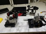
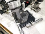
Here are the pictures of the axis. I just bought some random XY / X stages from ebay and mounted them. If you also pair it with a Noga indicator arm, you get an insane amount of freedom. You can solder anything to your hearts content with two of these.

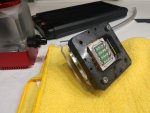
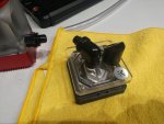
I also included the water cooling block I am working on to cool these. It is currently PLA plastic which will easily melt, but I will soon use high temp SLA resin to print the real thing once I get a design I like which will also hold the PCX lens.

This goes back to my original question in the projector optics question in the optics thread. What exactly is the optics that they use to focus/direct all the beams onto the phosphor wheel. It would make my life soooo much easier if I could just buy the projector and reuse the special optics that they use. Although, modifying the height of the multi lens + a PCX should do the job for me very well.
 

Attachments

  • IMG_20200513_014444521.jpg
    IMG_20200513_014444521.jpg
    341.7 KB · Views: 59
  • IMG_20200513_014502317.jpg
    IMG_20200513_014502317.jpg
    314.7 KB · Views: 58
  • IMG_20200513_014553381.jpg
    IMG_20200513_014553381.jpg
    267 KB · Views: 60
  • IMG_20200513_014602696_HDR.jpg
    IMG_20200513_014602696_HDR.jpg
    365.2 KB · Views: 55


Joined
Feb 12, 2016
Messages
589
Points
63
To focus blue beams on Phoshor wheel in PJs I dismantled there was a simple PCX lens (not round but shaped to be held in rectangular hoder), rest of optics was intended to combine colours and direct resulting beam onto DMD chip.
 

tedcs

0
Joined
Jul 27, 2012
Messages
48
Points
18
Thank you for sharing this.

I was extremely worried about the dust from cutting would get into the array. However, you shared above that there is a window to protect the array/mirrors. I am more confident in pursuing this now. I had initially thought you used some kind of chemical to soften the glue to avoid and production of dust.

I have multiple micrometer XYZ axis holders so I should be able to position it again.
What type of glue do you recommend? I have basic high viscosity UV glue cured by 350nm from loctite. I am wondering if you know of any more specific glues I should use for this precision job.

Sorry likevvii, I have no clue about glue.
I used Bondic Liquid Plastic Welder because that's what I have.
It seemed adequate.
 
Joined
Feb 25, 2010
Messages
1,643
Points
113
HMMMMMMMMMMmmmm ??? SO.....we want to employee a set of C-Lenses to remove the individual beam Astigmatic conditions ????
MMMM ???? Maybe not !!! Remember .....beam centration is a demanded condition as each individual beam propagates thru the physical Centre line of the C-Lens geometry !!!

SO....we have what.??? .. 24 individual beams generated by the array !!! For a C-Lens to work....the beam must pass thru the dead centre !!! How can 24 beams all pass thru the centre....Hahahaha....It is like when Mo, Curly and Larry tried to go thru a door way at the same time !!! It Just does not work !!! In this case....we have " 24 Stooges "....each needing to go thru the centre of the door frame !!! All cannot be centered !!!

Anyway.....Just my two cents !!! No extra charge !!!

CDBeam
 

WizardG

0
LPF Site Supporter
Joined
May 9, 2011
Messages
1,187
Points
113
I suppose if you had zen master level patience you could knife edge all the beams together with some combination of mirrors and prisms to get them all centered in the C-lenses. But I fear that down that path lies insanity.
 
Joined
Feb 25, 2010
Messages
1,643
Points
113
SO....so....How do ya get this......

o o o o o o
o o o o o o
o o o o o o
o o o o o o

Into ......Into what ??????

The ONLY option I see is to have ALL 24 LD's FAC'ed ????
Oh...That would be a treat !!!!....They are of a miniature size to start with.....NO I am afraid the C-Lens option is a Dead End !!!

OK....That said.....a question asked by LaserMicroscope has me thinking....plus the experiments by Styro......I MAY have a solution....Thanx guys for starting the wheels to turn !!! I must consider...and will post in a separate thread !! CDBeam
 
Joined
Feb 12, 2016
Messages
589
Points
63
Hi Bob,

Yes these new multiemitters from Nichia are totally different from single diodes what we have been correcting all the time, so a way to shape the "beam" has to be totally new and different as well I think.

My approach was to avoid using mirors etc. for each of 24 beams, but use just 10 custom made cylindrical lenses (4+6) for the total of 24 beams.
And yes, after expansion all the beams will be knife edged already, so no micromirrors would be needed.

Of course the final resut will not be perfect (will depend on the factory alignment of dye crystals on the base) but at least cylindricals could be tilted a little to improve orientation of any whole row of beams.

But these custom cylindricals have to be thin (<3.5 and <6 mm wide) and long enough to cover all the row. They would be placed where the beams expand to touch each other, so no plano concave lenses would be needed and all beams would result "knife-edged" after them.
And yes, each beam would pass through physical centers of the lenses!
Each lens could be tited a little on a holder. Holders could slide on construction bars. This would look like easiest setup to me to obtain a long range beam.
Which would not have very high energy density to pop baloons but low divergence to reach the moon!

Here is the sketch. This can be done with gang lens intact (here focal distance of cylindricals f2 can be estimated from tedcs picture in post 5) or with gang lens removed (here f3 would be shorter than f2). Metal parts (holders) are painted.

Also f2 and f3 are bigger than f1 (original focal of the gang lens shape) what means easier adjustment compared to readjusting the gang lens what likevvii wants to do...

All sizes I took from spec sheet of NUBM31, I do not know if NUBM34 has same dimentions.

10 cylindricals sketch.jpg
 
Last edited:
Joined
Feb 12, 2016
Messages
589
Points
63
Replying to your post 22:

We will get this into that drastically calming the divergence.

i i i i i i OOOOOO
i i i i i i OOOOOO
i i i i i i OOOOOO
i i i i i i OOOOOO
 

tedcs

0
Joined
Jul 27, 2012
Messages
48
Points
18
Replying to your post 22:
We will get this into that drastically calming the divergence.
i i i i i i OOOOOO
i i i i i i OOOOOO
i i i i i i OOOOOO
i i i i i i OOOOOO

While we are pondering methods to turn a sow's ear into a silk purse, it may useful to consider the intended purpose of this device. This has me wondering about the equipment in which it is used, I wish I knew more. I suspect that the diversity of diode characteristics is much larger than we find in single diode packages.
NUBM34 print negaitve.jpg
Defining the goal might be worthwhile, as well.
 
Joined
Feb 12, 2016
Messages
589
Points
63
Tedcs, do you have the spec sheet, are the dimentions of 34T same as of 31T?

You are right about diversity - nothing is perfect in life, but 20% of effort could be enough to deliver 80% of yield.
The intended purpose of all N. blocks seems to me to be focused at little inches to pump phosphor in (retro)projectors and to be used in laser cutters. I can (slowly) cut thin metal at 20cm with 2 side by side NUBM08 blocks focused together without any beams correction.

I am suggesting how to make a lower divergence / longer range laser beam from 31/34T just at "little" expense.

BTW my theory approach does not change the direction of the beam unlike common knife-edging and PBS combining would do.
 
Joined
Feb 25, 2010
Messages
1,643
Points
113
YIKES !!! Picture sez it all !!!
 

Attachments

  • Hair on Fire 2.jpg
    Hair on Fire 2.jpg
    77.9 KB · Views: 6

tedcs

0
Joined
Jul 27, 2012
Messages
48
Points
18
Tedcs, do you have the spec sheet, are the dimensions of 34T same as of 31T?
I have no specifications or dimensions, but I can measure the beam thermal print:
NUBM34 print dimensions.jpg
You are right about diversity - nothing is perfect in life, but 20% of effort could be enough to deliver 80% of yield.
This could be the theory of the "quick and dirty" approach.
It is important to recognize when 80% yield is adequate.
Also, is has been said that: "Good enough is the enemy of better."
In short, yes, I agree. :)

The intended purpose of all N. blocks seems to me to be focused at little inches to pump phosphor in (retro)projectors and to be used in laser cutters. I can (slowly) cut thin metal at 20cm with 2 side by side NUBM08 blocks focused together without any beams correction.
I am suggesting how to make a lower divergence / longer range laser beam from 31/34T just at "little" expense.

BTW my theory approach does not change the direction of the beam unlike common knife-edging and PBS combining would do.
NUBM34 print group.png 01-21-11-01-Walther-LGV-air-rifle-Hobby-pellet-target.png

The beam characteristics required for sending a modulated signal to Mars are different from those for a beam intended to punch a hole through metal.:D
Especially if making a hole costs as much as a beer, and making a beam for interplanetary communication costs as much as Monaco.
 
Joined
Feb 12, 2016
Messages
589
Points
63
Thank you for measuring, Tedcs. 18x14 mm is exactly as it was on the spec sheet of 31T.
So it means that thinner lenses for 34T have to be <2.8mm wide. Maybe better to do it with 31T where just <3.5mm would be fine.

Could you also evaluate the focal distances needed for such lenses? These would be distances where the beams (or better beam spots on your thermal paper because not all of the beam outer part is of value) start to touch each other like on your picture in post 5.
In both horizontal and vertical dimentions.
 

tedcs

0
Joined
Jul 27, 2012
Messages
48
Points
18
Thank you for measuring, Tedcs. 18x14 mm is exactly as it was on the spec sheet of 31T.
[...]
Could you also evaluate the focal distances needed for such lenses? These would be distances where the beams (or better beam spots on your thermal paper because not all of the beam outer part is of value) start to touch each other like on your picture in post 5.
In both horizontal and vertical dimensions.

L. Superglue, I believe I understand what you want. Yes, I think I can do that. What I can do more quickly is put a scale on the short axis image. It looks like the length is about ~2.5" or 63mm. For better results, I will need to set up a different arrangement and get some more images. lt will be interesting to see what patterns will result when the laser is operated at higher power levels. Beam scale s.jpg


Top