Welcome to Laser Pointer Forums - discuss green laser pointers, blue laser pointers, and all types of lasers

Buy Site Supporter Role (remove some ads) | LPF Donations

Links below open in new window

FrozenGate by Avery

Marx Generator!

Fiddy

0
Joined
May 22, 2011
Messages
2,726
Points
63
G'day,

Got the parts for this the other day!

For all of use who do not know, a Marx Generator works by charging capacitors in parallel then discharging in series, when you discharge in series you will add the voltages of the capacitors up.


This is done by the spark gap between each capacitor.
here's a diagram:

So-how-does-it-work.jpg


How i put i all together:

12V Battery -> HV Generator -> Marx Generator -> Output!


They are quite simple to build, if you've got a HV supply already its even easier.

marxgenerator.jpg


I used 7x 10kV 4.7nF Capacitors & 13x 1 M ohm capacitors, this one was just a test, i have 20x capacitors and 200x resistors waiting :)

Im currently using the per-assembled one that runs off 12VDC: MXA028: HIGH VOLTAGE DC GENERATOR BOARD 9-15 VDC PROJECT ASSEMBLED KIT | eBay


Thanks for looking!

Fiddy.
 
Last edited:


Thats so beautiful and the discharging sound is pure awesomeness.. Man are we Geeks !! XD
 
So where do I pay?

Just kidding. Really nice! Wouldn't mind making one eventually ;).

:beer:
 
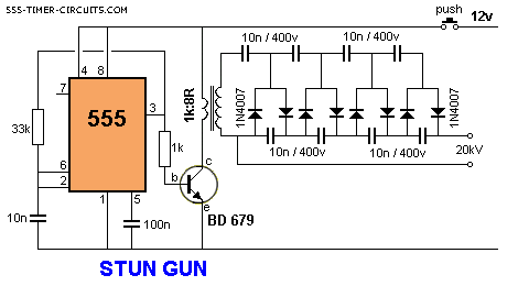
For "continuous" output....

StunGun.gif

That's not a "Marx generator" thats a Stun gun schematic... Cockcroft–Walton (CW) generator .. sort of. Also known as a voltage Cascade multiplier circuit.

Can be quite dangerous. They've claimed a few TV repairmen in the old tube TV days.
 
That's not a "Marx generator" thats a Stun gun schematic... Cockcroft–Walton (CW) generator .. sort of. Also known as a voltage Cascade multiplier circuit.

Can be quite dangerous. They've claimed a few TV repairmen in the old tube TV days.

I know what it is. I was just giving some info for a "continuous" output source for HV.

As for any HV application... safety is non-negotiable..
 
Last edited:
I don't quite see how that would work....the transformer is being driven in flyback topology, so the output would be just pulses, not true AC. There would be a little ringing down, but I don't think it would work too well.

Unless, you run it in resonance....
 
I don't quite see how that would work....the transformer is being driven in flyback topology ...

Unless, you run it in resonance....

Running it in flyback topology is technically running it in resonance, but only when you're using a feedback coil. Like the simple 2N3055 single transistor driver or whatever it is. That circuit isn't, which is why they specify a specific transformer resistance.
 
Last edited:
It's not resonant unless you find the resonant frequency. The simple 2N3055 driver does NOT drive the flyback at resonance. The arcs would be a lot and i mean a LOT larger than what they typically are for that driver.

Flyback topology utilizes the inductance of the primary coil to cause a sort of avalanche of energy to appear on the secondary...usually it's just one polarity, positive, and maybe a little bit of ringing due to capacitance and inductance. The closer you get to the resonant frequency the higher the voltage and the more pronounced the ringing becomes, up until you're not even outputting pulses anymore but a sine wave.

Using one switch is called "quasi resonant" topology when it is outputting a sine.
 
I dunno about you, but I've had some pretty massive arcs from the single transistor driver ..

The only way that driver works is because it relies on the flyback resonating. If it wasn't, the driver would just latch on continuously and pop the transistor. The feedback coil provides the resonant frequency switching, that's the idea. Drivers like the ZVS driver use the same method, however they have better switching circuitry to allow you to pump insane amounts of power into the transformer.

The resonant frequency changes as you draw an arc - you can hear the driver even adjust for this.

The principle of operation is as simple as the circuit itself: When power is applied, the transistor will conduct the current allowed through resistors into the flyback primary, causing it to induce a current on the secondary, and, at the same time, on the feedback winding. This feedback current will trigger the transistor to stop conducting, and as the magnetic field in the ferrite core collapses, a large HV spike will appear on the secondary windings (basic inductor action). But now there is no feedback current to keep the transistor off, so it will once again conduct, and the cycle will repeat, at a natural frequency that puts the transformer in resonance, resulting in enormous voltage gain. One of the advantages of having a feedback winding is that the circuit becomes dynamic: The frequency of operation is automatically adjusted to resonance, depending on many factors. It is interesting, because you can actually hear the frequency change as you draw an arc (high loads drop the frequency to a high pitched 20Khz whine which than becomes ultrasonic as the arc grows).
 
Last edited:
That's wrong... because the driver works on saturation.

As the transistor is on, current flows, like what he said. The ferrite core eventually begins to saturate, eventually causing the feedback winding to stop feeding back. This turns the transistor off, and then as the core de-saturates, the transistor is allowed to turn back on (due to the biasing resistors) causing the cycle to repeat thousands of times a second. It's how camera flash inverters, joule thieves and single transistor flyback drivers work. As you draw an arc, you're changing the saturation current causing the transistor to turn off/on faster.

If the flyback was in resonance then the arcs would be enormous, like 7-9 cm long arcs. But they aren't, because of the way it works.


Now, for a ZVS driver, yes, that works on resonance; but only primary side resonance. If both the primary and secondary side are in resonance the flyback would explode or be destroyed from the huge amount of voltage buildup due to the lack of a load...resonance cancels out the inductance and capacitance causing only resistance to remain.

And that resistance doesn't do much to limit the voltage, so it rises to huge levels. That's actually how (some) Tesla Coils work too!
 
Last edited:


Back
Top