Welcome to Laser Pointer Forums - discuss green laser pointers, blue laser pointers, and all types of lasers

LPF Donation via Stripe | LPF Donation - Other Methods

Links below open in new window

ArcticMyst Security by Avery

LaserBee VS Ophir. What is this?

ARG

0
Joined
Feb 27, 2011
Messages
6,772
Points
113
I am having some issues with my LPM's. I own a LaserBee 3.2W and an Ophir 20c head.

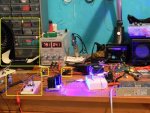
I have an M140 in an Al block with a TEC to chill it and a CPU heatsink w/fan for the top side of the heatsink. The Ophir and LaserBee's sensor area's are level, and when the Ophir is in use, it is perfectly centred.
BYToO.jpg

The PCB on the left has a circuit to take the 9V battery also seen on the left to -9V and +9V. The supply is very clean from what I can see on the scope.

My problem is that my LaserBee's readings are VERY different from my Ophir readings.

OMy2v.png

This is a reading from the LaserBee. At 50 seconds I turn on the TEC and CPU heatsink fan from the power supply seen on the right of the first picture. As you can see, the reading is all over the place on what I assumed to be a stable laser.

When I measure this with my Ophir the readings (from my FLUKE DMM) are +/-1mW without the TEC and 100% stable with the TEC after 5 minutes to equalize. No massive change as seen in the LaserBee Graph.

What is causing this huge difference in readings? I thought the Ophir would have shown more instability in the laser since the response time is faster.
The fan is very very slow, and the air is sucked in from the top and comes out the sides perpendicular to the sensors, so it is not that.
My best guess is noise from the PSU when I turn it on, but would it cause that monster of a graph? I added an RF choke to the TEC cord with a couple of turns around it and it didn't seem to have an effect.


Joined
Feb 1, 2008
Messages
2,894
Points
0
Maybe check for any stray capacitance in your amp's input?

Is an op amp oscillating? Oscillation can be a mode of failure...

All grounds are referenced to the same place?

Has your TEC sensor been recently dropped?

Any signs of wear on the TEC wiring?
 

ARG

0
Joined
Feb 27, 2011
Messages
6,772
Points
113
Maybe check for any stray capacitance in your amp's input?

Is an op amp oscillating? Oscillation can be a mode of failure...
I'll check

All grounds are referenced to the same place?

What does that mean?

Has your TEC sensor been recently dropped?

Any signs of wear on the TEC wiring?

Never. I have kept the TEC sealed when not in use and it is in perfect condition. The cable is fine too.
 
Last edited:
Joined
Oct 26, 2007
Messages
5,438
Points
83
First try isolating the problem. Is it the meter head? The PSU? The TEC/heatsink? Try turning on the TECed laser, and measure some other laser with the meters. Be sure to put something between the TECed laser and the meters (like a book) to block any ambient temperature differences.

If the readings are still all over the place, it's probably something related to the power or something like that. If the other laser meters just fine, maybe something like the TEC/fan is affecting the ambient temperature? Remember that you put a book between the meters and TECed laser. Try testing for the effect of the TECed laser by turning on the TECed laser, not separate the two with a book, and metering the other laser too. Maybe the TEC + fan is affecting the ambient temperature that the Laserbee is reliant on; the Ophir head has a much larger mass after all.
 
Last edited:

Blord

0
Joined
Dec 24, 2007
Messages
5,356
Points
0
How much mW was the Ophir head measuring the output ? You said it was stabilizing around a value with +/-1mW.

And what BB said, try to isolate the problem. Run the laser on batteries without the TEC and see what happens on the Laserbee LPM. The graph should show a steadily declining output.
 
Last edited:
Joined
Apr 2, 2009
Messages
10,662
Points
113
+2 to those who are helping- +3 for ARG- good thread- nice pics- can you stop by and organize my workspace=lol
GL finding a solution{not sarcasm}-- hak:D
 
Last edited:
Joined
Jul 27, 2007
Messages
3,642
Points
63
The problem is that the laserbee is unstable, the Ophir readings are stable.

The laserbee graph makes no sense to me for a diode laser, maybe Jerry can shed some light on the issue.
 
Joined
Oct 26, 2007
Messages
5,438
Points
83
No, it's not that the Laserbee is unstable. After all it is reading the diode laser power just fine before 50s. It's that turning on the TEC + fan causes some instability for some reason, and that's what we're trying to figure out.

Hakzaw1 is so right about that being a nice and clean desk. My desks are so covered in parts and half-completed projects.
 
Joined
Feb 23, 2012
Messages
1,282
Points
0
Is this the case for all lasers or just one?

Good luck! :beer:
 

Trevor

0
Joined
Jul 17, 2009
Messages
4,386
Points
113
So, just to make sure I understand properly:

When you use the Ophir sensor, no change occurs in the reading when you turn on the TEC and fan.

When you use the LaserBee, the readings become unstable when you turn on the TEC and fan.

Could the TEC and fan be adding electrical noise to the LaserBee? Seems possible, since the Ophir sensor is sort of shielded, whereas the LaserBee is not really protected from electrical noise in its deluxe plastic box.

Trevor
 
Last edited:
Joined
Sep 20, 2008
Messages
17,622
Points
113
I just saw this Thread ARGL...
Could you clarify a few things in the pic before I try to
make a determination or guess????

1) you have one 9Volt battery hooked to a breadboard.
What circuit are you using to produce +/- voltages for
the OPHIR head ??

2) what is that circuit and where is it hooked in ??

3) what is that and is it electrically connected anywhere??

4) the blade of this fan seems to be stopped but perhaps
you have a very fast camera. The PostIt notes seem to be
acted upon by an air stream.

What is the PS (that reads 791 and 4.1) connected to??

What is the Switching PS (at the lower right of the pic)
connected to??

I'm just asking questions to rule out a few things.


Jerry

You can contact us at any time on our Website: J.BAUER Electronics
 

Attachments

  • Arg-Ophir-LBII-1.JPG
    Arg-Ophir-LBII-1.JPG
    85 KB · Views: 266
Last edited:

ARG

0
Joined
Feb 27, 2011
Messages
6,772
Points
113
I wasn't feeling the greatest yesterday so I didn't mess around with this much, I will try to get some more results today. I have some 18 bit ADC's so I'm going to hook my Ophir up to one of those then into an Arduino so I can graph the power that the Ophir is showing. I'll also throw together an OPA circuit and use that with the laserbee TEC to see what it changes.

@Blord I forgot what power the Ophir was showing.

@BB Will do, I'll try out everything and post the results.

@Trevor that is exacly what is happening. The LaserBee circuit is enclosed.

@Jerry
1. I forgot the IC name, but it takes the +9V and GND and makes 9V+ GND and 9V- The results are the same with two 9V batteries, but for the sake of the experiment I'll use two 9V batteries to make sure the supply is clean.
2. It's a different project I've been working on, it's not hooked into anything.
3. It's an RF choke with the laserbee cord wrapped around it.
4. The fan isn't of, the sticky note is just wedged up against the fan so it looks like it's on.
PS is connected to the diode.
Switching PS is connected to the Fan/TEC
 

Trevor

0
Joined
Jul 17, 2009
Messages
4,386
Points
113
OpenLPM + StampPlot Pro? :D

Your LaserBee in its enclosure is pretty close to the laser and your power supply in that photo... maybe try moving it around your desk to see if the behavior of your graph changes? Might help you diagnose if it is electrical noise, and if it is, what is causing it.

Trevor
 

ARG

0
Joined
Feb 27, 2011
Messages
6,772
Points
113
I'm actually working on my own program to interface with Open LPM for the Ophir head :D I'm going to add a color LCD to the Ophir as well, for on board graphing :) Hopefully that's not biting off more than I can chew.
I never got stamp plot to work for me for some reason, it didn't detect my COM ports. That doesn't really matter anymore since I already have something working for real time graphing.
 

Benm

0
Joined
Aug 16, 2007
Messages
7,896
Points
113
OpenLPM + StampPlot Pro? :D

Your LaserBee in its enclosure is pretty close to the laser and your power supply in that photo... maybe try moving it around your desk to see if the behavior of your graph changes? Might help you diagnose if it is electrical noise, and if it is, what is causing it.

Trevor

Don't you think this could have been cause by one of the 'kinks' in the laserbee calibration plot you discovered? Perhaps the change in optical power is just minimal, but its just at a privot point in the calibration giving these huge variations.

One way to resolve that would be to repeat this experiment at, say, 80% of the diode current you are using, so you're measuring in the different range of the laserbee. Perhaps it will then read quite stably too, as you ophir sensor does.
 
Joined
Sep 20, 2008
Messages
17,622
Points
113
@Jerry
1. I forgot the IC name, but it takes the +9V and GND and makes 9V+ GND and 9V- The results are the same with two 9V batteries, but for the sake of the experiment I'll use two 9V batteries to make sure the supply is clean.
2. It's a different project I've been working on, it's not hooked into anything.
3. It's an RF choke with the laserbee cord wrapped around it.
4. The fan isn't of, the sticky note is just wedged up against the fan so it looks like it's on.
PS is connected to the diode.
Switching PS is connected to the Fan/TEC

1) the "IC" that can produce +/- voltages usually uses
some kind of switching circuit that could transmit spikes.
Using 2 9V batteries as you suggest would rule that out.

2) OK

3) Which LaserBee Chord is rapped around it and why.
We don't supply a choke because we found no reason to
need one.

4) OK

Try removing all wires that run under the LaserBee enclosure
and its Thermopile cable.

Try turning off just the LD. Then try turning off just the Fan.
Then both the LD and Fan to see if the readings stabilize.
You will need to do the separate tests over at least a minute.
Finally turn off the TEC.
This should help to hunt down what's causing the variations.

BTW even if a fan is not blowing directly at a Thermopile it still
creates air currents in the vicinity. Your fan seems to be about
6"-8" from the sensors.

The OPHIR head electronics is enclosed in a massive metal shell
and easily rejects external electrically produced noise and EMF
spikes (PS) much better than a plastic enclosed sensitive circuit.


Jerry

You can contact us at any time on our Website: J.BAUER Electronics
 
Last edited:


Top