Welcome to Laser Pointer Forums - discuss green laser pointers, blue laser pointers, and all types of lasers

Buy Site Supporter Role (remove some ads) | LPF Donations

Links below open in new window

ArcticMyst Security by Avery | Browser Hide by Avery

Knife-edging four NUBM44 in Lasertack micro module

Joined
Feb 12, 2016
Messages
589
Points
63
This project was inspired by former avatar of Alaskan.

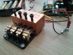
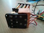
This is my first experience in knife edging of multimode LDs, so I tried to prepare well - last year I asked CDBEAM to make me a Quad Heatsink-Holder for four 12mm DTR modules from a solid block of copper. It should replace the small Al LDs holder in the original Lasertack set because this one for sure would not be good to absorb and evacuate heat produced by four working 6W lasers.

CDBEAM also provided fixing screws for all modules and made additional hole in the micro baseplate to fix this heavy Cu chunk well.

After that I did some add-ons to the set up: made side and bottom holes for set screws to fix the back parts of the DTR modules what allowed me to take advantage of the CDBEAM’s set screws to fix focusing rings. I did this because I did not want to use teflon tape for fixing G-2 barrels in focus to infinity positions. Maybe wrong but we will see…

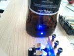
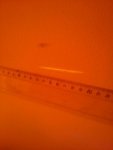
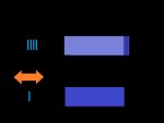
Finally, I glued the prism mirrors, assembled the device and adjusted the beams with all LDs connected in series at 450mA current. From the 3rd and 4th pictures I suppose that I have knife edged LD1 &2 pretty well (no gap visible), but between LD2, LD3 and LD4 spots there are gaps of ~1mm what I think is due to mount positions (once prism mirrors are glued you cannot move the mounts left-right).
Did I do it right of do I need to try adjusting all four spots so that there would be no gaps between spots at all?

Anyway once adjusted - the spot on the wall at 5m is the line ~6-7cm long. So it does look OK, does not it?
 

Attachments

  • a.jpg
    a.jpg
    67.8 KB · Views: 327
  • b.jpg
    b.jpg
    61.7 KB · Views: 254
  • c.jpg
    c.jpg
    60.7 KB · Views: 317
  • d.jpg
    d.jpg
    57.7 KB · Views: 196
  • e-v.jpg
    e-v.jpg
    17.5 KB · Views: 186
Last edited:


Good work, the only thing I find troublesome with 44/47 diodes is that rapid divergence, I had thought to correct each beam before the KE, is it possible to correct all 4 llll now that they are side by side? As they sit won't they diverge into each other? That is the narrow portion of each line will widen rapidly and they will all overlap.
You may be able to use cylindrical beam correction on all 4 at once.
 
Last edited:
That is awesome-ness, 4 44's together. :drool: Best wishes with your build, if you can, love to see some beamshots from this puppie. :gj:
 
Last edited:
Me too think that |||| will overlap rapidly, dimentions of Lasertack micro baseplate do not allow correction before KE, if you would try doing this you have to produce a custom baseplate...

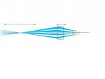
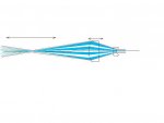
Indeed the gap between lines may not be an issue because the idea of this experiment is to make a "focusing expander" which would allow to focus all the beams in one small area at said distance by slightly changing distance between cylindrical lenses (and beams expansion before focusing would allow to focus them better at Rayleigh distance if I am correct). Here I tried to do a sketch in Paint.

Unfortunately now I can only use 3x cylindricals because the width of my |||| group entering PCV lens is ~4mm, so for 6x expansion I would need a PCC >24mm wide!

Edit: Sorry, I meant PCV >24mm wide!
 

Attachments

  • Focusing expander.jpg
    Focusing expander.jpg
    18.5 KB · Views: 129
Last edited:
From what I can see in your third and forth photos, you still need to adjust knife edging to bring each beam over the others. They all seem to be more separated than necessary. You should be able to deal with the divergence after this, if you are so inclined.
 
Last edited:
Paul those gaps don't matter at all, they will be expanding over those gaps in just a few feet, what looks like l will become =====

The lines that look tall will diverge quickly to be a little taller but a lot wider, it's the horizontal divergence that will be very aggressive.

56229d1496608450-knife-edging-four-nubm44-lasertack-micro-module-horzesp.jpg
 

Attachments

  • horzesp.JPG
    horzesp.JPG
    45.1 KB · Views: 502
Last edited:
MMMMm....the problem is that the slow axis....MUST enter directly into the centre of the Cylindrical optics... So...

When you knife edge....you end up with a geometry of llll

Now....when you have one LD ...... you have a geometry of l

which can be aligned on the center of the first Cylindrical lens...the Plano

concave........But....when you have four (4) beams....like this llll

you CANNOT center.....SO....

One must Cylindrical correct each beam....THEN .... knife edge combine the

beams...AFTER they are corrected.

Now....I have NOT done this...but see NO reason the optical path could not be

arranged. Sorry Vlad...I see no other way.....and...until I CAD it out....I am

NOT positive this can be done. The 044 is just an unruly Bastard. :(:(:(

Beam out
 
There is another way, anamorphic prisms. I'm trying to remember if there's a way to do it with the cylinder pair too...
 
What I want to do here with moving C-lenses is not only expand each of stacked beams but to focus all of them in the same small area.

Let me better explain the idea of this experiment (and correct me if I am wrong!):

Let’s consider that we do not have 4 blue stacked beams IIII but one wide beam around painted in red. Let me suggest that each photon the blue beams consist of would correspond to a photon in the imaginary red beam and propagate through C-lenses in the same way. The red beam also includes the gaps between blue beams which “propagate” exactly as beams do – expand at beam expansion and tighten at focusing…

Red beam here is perfectly centered. So will the IIII group be (let’s regard it as a group).

By slightly changing lens separation from the perfect one where focal points coinside (as in beam expander) we can get either diverging or converging red beam as a result. What means that all 4 blue beams “caught” inside of the red imaginary one would not only be focused at the same distance but also pass through the same focus point on the optical axis drawn through the center of IIII group and lenses centers.
For sure it will not be a tiny focus point but the area which would correspond to the “beam waist” of the red beam because we have to take divergence after C-lenses into account. And from what we know about light propagation – expansion of the red beam before focusing will help to reduce its divergence and allow to concentrate it on the smaller beam waist area at distance.
So should be the case with the blue IIII group as well.
 

Attachments

  • Focusing expander - beam waist range.jpg
    Focusing expander - beam waist range.jpg
    20.1 KB · Views: 141
Last edited:
It's possible Yes, at least I think so, but because the 44 has that very aggressive axis your lenses will need to be within a margin and just how far you can converge the beams before they diverge is the question.

Your convex will likely need to be bigger than your concave and how far apart they will need to be working is in the math, but if you could obtain a reasonably tight spot at 5 to 20 feet that would certainly be fun, but I doubt you can get any real distance because of that one very aggressive axis.

I would enjoy 4 x 44's all packed into a burning spot at 5 to 20 feet, that would be fun, it's just a tough diode to work with, if you were using half watt 405nm diodes or quarter watt 660nm diodes it would likely work very well into the far field.
 
Last edited:
Thank you for sharing your project with us, looking forward to seeing how the issues are worked out. Regardless of the unruly behaviour of that diode for expanding them together, they can make a hell of a lot of power for burning things close up when stacked like that. Even if you don't expand the beams or correct them, I would be particularly interested in seeing a beam shot in a darkened room.
 
Last edited:
What I want to do here with moving C-lenses is not only expand each of stacked beams but to focus all of them in the same small area.

Let me better explain the idea of this experiment (and correct me if I am wrong!):

Let’s consider that we do not have 4 blue stacked beams IIII but one wide beam around painted in red. Let me suggest that each photon the blue beams consist of would correspond to a photon in the imaginary red beam and propagate through C-lenses in the same way. The red beam also includes the gaps between blue beams which “propagate” exactly as beams do – expand at beam expansion and tighten at focusing…

Red beam here is perfectly centered. So will the IIII group be (let’s regard it as a group).

By slightly changing lens separation from the perfect one where focal points coinside (as in beam expander) we can get either diverging or converging red beam as a result. What means that all 4 blue beams “caught” inside of the red imaginary one would not only be focused at the same distance but also pass through the same focus point on the optical axis drawn through the center of IIII group and lenses centers.
For sure it will not be a tiny focus point but the area which would correspond to the “beam waist” of the red beam because we have to take divergence after C-lenses into account. And from what we know about light propagation – expansion of the red beam before focusing will help to reduce its divergence and allow to concentrate it on the smaller beam waist area at distance.
So should be the case with the blue IIII group as well.

Hmmm ????? Your Ray path drawing may work....It will deliver a convergence point....not an infinity focus....but....it is a convergence point that you want !!!

EXPERIMENT....and provide us pics....so that we may learn !!! PLEASE !!!!!
:o:o:o...... Thanx...

CDBEAM

Added Blah.Blah.....I still say....that it is possible to have an IR range finder.....constantly measuring the distance from the LD source....to the " target "....down range in the Far Field....and have that data stream....control a micro translation table. This table would move back/forth as a function of the Range Finder telemetry. The Plano Convex lens would ride on this table.

SO.....the Convergence point would terminate at the target location. AUTOMATICALY !!! Of course.....the convergence point range must be within the limits of the optics....and such a setup ....mmmmm....may not be possible on a Hand Held unit.....mmmmm...unless one hacks the auto focus unit from a cheap digital camera ??
MMmmmmm ???
 

Attachments

  • DocBrown It Could work 2.jpg
    DocBrown It Could work 2.jpg
    130.6 KB · Views: 71
Last edited:
What I want to do here with moving C-lenses is not only expand each of stacked beams but to focus all of them in the same small area.

Let me better explain the idea of this experiment (and correct me if I am wrong!):

Let’s consider that we do not have 4 blue stacked beams IIII but one wide beam around painted in red. Let me suggest that each photon the blue beams consist of would correspond to a photon in the imaginary red beam and propagate through C-lenses in the same way. The red beam also includes the gaps between blue beams which “propagate” exactly as beams do – expand at beam expansion and tighten at focusing…

Red beam here is perfectly centered. So will the IIII group be (let’s regard it as a group).

By slightly changing lens separation from the perfect one where focal points coinside (as in beam expander) we can get either diverging or converging red beam as a result. What means that all 4 blue beams “caught” inside of the red imaginary one would not only be focused at the same distance but also pass through the same focus point on the optical axis drawn through the center of IIII group and lenses centers.
For sure it will not be a tiny focus point but the area which would correspond to the “beam waist” of the red beam because we have to take divergence after C-lenses into account. And from what we know about light propagation – expansion of the red beam before focusing will help to reduce its divergence and allow to concentrate it on the smaller beam waist area at distance.
So should be the case with the blue IIII group as well.

The far-field spots can be made to overlap as shown. The more the beam is expanded the larger the "gaps" on the output lens of the expander will get.

You will need to make a modification to your knife edge set-up. The distance from each diode to the input of the BE has to be equal. Otherwise the BE can't focus the individual beams together. You will have to "step" the modules back in the copper base. Looks like you have the room, just need to re- drill/tap the holding screws.
 
LS....VERY good to see you here !!! Glad you agree that this arrangement is feasible !

I have never tried to run a Quad group thru a set of cylindrical's !! Should be interesting !!

Later,
Beam Out
 
I always liked Christopher Lloyd. Saw him in Taxi first as the stoner hippie that was sooo spaced out. :crackup:
 
Hi logsquared,

Yes, I agree that for perfect spot it would be better that all beams have same path distance before BE but this would make the set up more complicated. In this set I am trying to make use of as little pieces as possible and that these pieces could mostly be taken off shelf.
And the difference in path of 1st and 4th beam is only 4cm – so I think that the distortion caused by this would not be as much as e.g. a non proper circular adjustment of C-lenses could cause… Anyway it is just experiment – not a product for a customer (however, if anyone is ready to sponsor this research…?).


Hi CDBEAM,

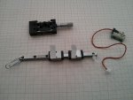
The autofocus thing was indeed one of my intentions. We also talked with RC about it once last year. But engineering the idea into hardware is not clear to me. Up to now for this project I have bought these 3 things:
- smallest linear rail guide found on Ali (5mm rail and 12mm guide width). Optlasers C-lenses perfectly pass here and can slide manually but do not hold position well. And today I do not see these rails on Ali any more, the smallest are 7mm wide now.
- Newport MS-200M-X from ebay – it holds position but how to motorise the knob?
- The smallest linear actuator from Ali – not checked how to drive it and apply it in the set.

Then your Big cylindricals would move on the rail and that’s it.
 

Attachments

  • z.jpg
    z.jpg
    105 KB · Views: 114


Back
Top