Welcome to Laser Pointer Forums - discuss green laser pointers, blue laser pointers, and all types of lasers

Buy Site Supporter Role (remove some ads) | LPF Donations

Links below open in new window

FrozenGate by Avery

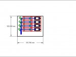
Knife-edging four NUBM44 in Lasertack micro module

A little update on the project.

When time was available this summer I tried to fight the aberration.
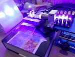
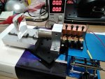
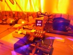
Thinking that this aberration of external beams was the result of higher refraction angles with Optlasers/Bob lenses which have pretty short f (designed for short setups) and high curvature, for my experiments I purchased some cylindricals from Thorlabs, among them ones with f = 75mm and -12.7mm, so 6x expansion could be done with lens separation twice longer than on previous pictures (pic. 1).
I suggested that longer lens separation and lower curvatures would also mean lower refraction angles of beams and reduce aberration to some extent.

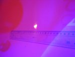
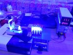
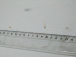
Well, the spot at 2m (500 mA) became a little (1-2mm) shorter than on setups I had before and paper sheet was igniting at 1A now and not at 1.2A like before (pic. 2). But this change was not drastic – a little more concentrated focus but still not square.

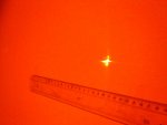
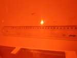
Now at 5m (here 1A current, pic. 3): it is clear to see that highly refracted out of center beams focuse closer than internal beams (sketch on pic.7). Here I show what the spots look like if the wall would be at different distances. Sorry for awkward hand righting.
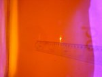
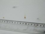
Pic. 4 shows all 4 spots when they separate again after focus range (beam waist range).
On pic. 5 two internal spots focus and combine pretty well (on line marked f 2,3 on the sketch) but two external beams are already diverging after their focus line (marked as f 1,4 on the sketch).
On pic. 6 you can see the shortest combined spot of 4 all beams if the wall is between f 2,3 and f 1,4 lines. Spot dimensions ~10x5mm.

Another thought I had was that the beams may not be perfectly parallel, if so – this could be a reason for combining beams so badly alternative to aberration.
Indeed the micro size of all Lasertack mirror mounts makes it really tricky to align properly what may be not an issue at 2m distance, but comes into action at 5m+... But from what I know aberration must lead exactly to what I see here – outer beams focusing closer than internal beams!

Do you agree?


Nice results! Aberrations are one of the tradeoffs you make with cylindrical lenses vs anamorphic prism pairs, although you can achieve higher magnification with a cylindrical lens pair. Alignment is far more touchy with the cylindrical lens pair.

Next thing I'd try is a regular Keplerian telescope (even 1x) using spherical optics and a spatial filter after your corrective optics, that should clean up some of the noise and result in improved divergence/beam quality. Hell with 4 NUBM44s you can probably punch your own spatial filter in a razor blade rather than buying ready made spatial filters.
 
Last edited:


Hi Diachi,

Do I get it right thinking that these Acylindrical lenses have the exactly purpose to avoid such aberrations what I saw in my setups?
https://www.thorlabs.com/newgrouppage9.cfm?objectgroup_id=5931

But from those prices one can suggest that these type of optics are not very common – aspheric, achromatic etc. lenses are much cheaper and available from many suppliers, but this was the only place (with prices) google sent me to after typing “Acylindrical”.

A question:
could there be a smart way to make a setup with aspheric lenses which would do “a kind of” what cylindricals do here without aberrations? Or add 1x aspherical expander to the setup just to compensate for aberrations which resulted from cylindricals (if makes sense at all)?
 
A little update on the project.

When time was available this summer I tried to fight the aberration.
Thinking that this aberration of external beams was the result of higher refraction angles with Optlasers/Bob lenses which have pretty short f (designed for short setups) and high curvature, for my experiments I purchased some cylindricals from Thorlabs, among them ones with f = 75mm and -12.7mm, so 6x expansion could be done with lens separation twice longer than on previous pictures (pic. 1).
I suggested that longer lens separation and lower curvatures would also mean lower refraction angles of beams and reduce aberration to some extent.

Well, the spot at 2m (500 mA) became a little (1-2mm) shorter than on setups I had before and paper sheet was igniting at 1A now and not at 1.2A like before (pic. 2). But this change was not drastic – a little more concentrated focus but still not square.

Now at 5m (here 1A current, pic. 3): it is clear to see that highly refracted out of center beams focuse closer than internal beams (sketch on pic.7). Here I show what the spots look like if the wall would be at different distances. Sorry for awkward hand righting.
Pic. 4 shows all 4 spots when they separate again after focus range (beam waist range).
On pic. 5 two internal spots focus and combine pretty well (on line marked f 2,3 on the sketch) but two external beams are already diverging after their focus line (marked as f 1,4 on the sketch).
On pic. 6 you can see the shortest combined spot of 4 all beams if the wall is between f 2,3 and f 1,4 lines. Spot dimensions ~10x5mm.

Another thought I had was that the beams may not be perfectly parallel, if so – this could be a reason for combining beams so badly alternative to aberration.
Indeed the micro size of all Lasertack mirror mounts makes it really tricky to align properly what may be not an issue at 2m distance, but comes into action at 5m+... But from what I know aberration must lead exactly to what I see here – outer beams focusing closer than internal beams!

Do you agree?

First...Vlad...Thanx for sharing your Quad 044 results. I am not surprised that that the use of a single set of C-Lenses with a quad beam input is giving less than desired results. I thought this might be a problem....but was unsure !!

C-Lenses are great, but..the beam propagation must entre the geometrical centre of the lens footprint..and with the " llll " arrangement...this does not happen. So...this is why we get different degree's of correction....when the beams are off-centre. SO....now what ??

OH...and my suggestion of just rotating each LD to a Stacked/Horizontal Knife edge design...is Flawed...for...one must then 90 degree rotate the C-lens set-up....and we end up with the same problem...beams not centred on the Plano Concave.

I fear you must use a separate C-Lens set-up...for each 044 LD unit. SO...correct each beam...then knife all four (4) beams.

Another point you mentioned...the possibility of the beams not being in a parallel relationship !!

Well....I think...that the root cause lies with the Physical/geometry relationship between the 12 x 30 modules case OD...and the pressed fit LD beam axis ! After many, many frustrating hours...at achieving final alignment with the " Cyan Cannon " build... my conclusion is that a " LD Pressed Fit " can be a problem...with Combiner/ Multiple LD builds.

I speculate...that even a very small off-axis condition...like 0.10 degree... will cause the beam propagation axis to not be in a perpendicular relationship to the 12 x 30 case OD. This then means...as the beam leaves the 12 x 30 module...it comes out crooked !!

OK...this may never be a concern with a single beam....but in a Combiner/ Multiple LD/ Quad build...it will cause a great amount of alignment problems. We can work around this with bounce mirrors or Knife Edge optics....but...for me...it is a huge headache !!!

Due this conclusion, I have come to the point...that...never again will I employ the 12 x 30 Module Press fit design in a Combiner build. I will instead use a LaserShowParts LD mount...or...if I have room...the Terrawatt Labs " Ultra Mount " design.

These designs use a friction fit between the LD and the mount and therefore deliver a much more precise LD to mount ...perpendicular relationship. Also...with these mounts...Pitch and Yaw adjustment can be done if demanded.

Anyway...we try, we experiment...and we learn !!
Beam out
 
Last edited:
Hi Diachi,

Do I get it right thinking that these Acylindrical lenses have the exactly purpose to avoid such aberrations what I saw in my setups?
https://www.thorlabs.com/newgrouppage9.cfm?objectgroup_id=5931

But from those prices one can suggest that these type of optics are not very common – aspheric, achromatic etc. lenses are much cheaper and available from many suppliers, but this was the only place (with prices) google sent me to after typing “Acylindrical”.

A question:
could there be a smart way to make a setup with aspheric lenses which would do “a kind of” what cylindricals do here without aberrations? Or add 1x aspherical expander to the setup just to compensate for aberrations which resulted from cylindricals (if makes sense at all)?

I think it's great that you are continuing to experiment with trying to knife edge and correct four NUBM44 beams. I don't see any way of getting what you are looking for with aspheric lenses as the best you can hope for is a BE effect. With one axis being wildly divergence I don't see a way around trying to correct for that axis first. CDBEAM is probably right in that to get the effect you are looking for, each beam needs cyl lens correction before knife edging. You can then use BE to get a better combination. +rep.
 
Last edited:
Well...MMMMmmm ?? Sometimes I am right ! :drool:

Maybe...once a day...the rest of the day....I am full of $hit !!! :D:D
You just gotta figure out...which is which !! :thinking::thinking::thinking::thinking:

But...for sure...If four (4) sets of C-lenses are demanded....this makes SG's set up....an Order of Magnitude...more complex !!

Just added a drawing I did...for a quad with four (4) C-lenses /044E...This is how I would now proceed....with each LD having a dedicated C-lens Optical set...Later...

:san::san::san:

CDBEAM
 

Attachments

  • 044-Q-COEB V2.JPG
    044-Q-COEB V2.JPG
    60.9 KB · Views: 252
Last edited:
Agree. Thanks for the drawing. On side-to-side diode setup this is (as I know) the only way to get the same divergence/beam size each beam. A single cyl set is possible but beam length path for each diode must be the same when reaching the 1st CV. Because all we know distance from cyls affects diode expansion so divergence as well. So single cyl is not going to work well on side-to-side +knife diode setup, even if you vertically stack to pass all beams thru cyls center, which is fully mandatory as other members pointed. Again, this is because of different length beam paths.

Moreover Bob, to get a small beam as possible for a better brightness (more energy density)...I'd like to recommend going with F2 lens and tilt 90º diodes/cyls. So you expand on the vertical axis. Then you can knife like this llll (side by side on the uncorrected axis). This way single beam is going to be about 2mm width x 6-8mm tall (depending on your expansion). So about 8mm width x 7mm tall 4 diodes combined. For smaller beam PBS combining is required.
 
Last edited:
Thank you guys for proposals but my plan was to make a set which would pass into the body of a portable headlight what means max. 92mm wide baseplate and this would not allow too many lenses to be on it for each beam. But it could be made longer than it is now.
That´s why I do not go by obvious paths but try to find a smart way around…Yes, Bob, I am also building a device to combine 2 NUBM06 with 2 NUBM 07 like you do with other LDs but these “perfect” beams you know would hardly reach 20W and is there anyone who does not want more? And I just have so many 44s to play with…

The beam stacking I have is not exactly IIII but II II, so there is still place for 5th beam in the center and the results I try to obtain could also be later applied for 5 KEdged beams.

So here is the spot at 5m and 4.5A (pic. 1 & 2 which I took for Alaskan especially). The divergence looks high and maybe is due to beams not being perfectly parallel, too.

But anyway, from only 2 internal beams at 4.5A the spot is much more concentrated (pic. 3) even if their staking is not tight but like I I with a gap in the center where one more beam could be placed. So, maybe for KE of 2-3 beams my idea could work in a way better than for 4-5?

Interesting, however, is that the 5 beams spot is also big in vertical dimention, so a normal Sanwu BE would be good (Greetings to Red Cowboy!) to expand/focus the beam vertically.

I tried to add it in between (pic. 4) where the beams pack was still tight enough to enter, but even with biggest 3x cylindricals I have the essential part of the now 3x3 = 9x expanded beams pack was lost. Finally I have ordered a bigger 50x50mm lens from Thor (159EUR+ tax!) and we will see the results later…
 

Attachments

  • 1.jpg
    1.jpg
    33.4 KB · Views: 84
  • 2.jpg
    2.jpg
    55.7 KB · Views: 100
  • 3.jpg
    3.jpg
    37.5 KB · Views: 63
  • 4.jpg
    4.jpg
    76.3 KB · Views: 146
Last edited:
Interesting results LS :)

I was going to draw this but CDBeam did a better job already, this knife edged output could then be fired into an adjustable beam expander.

57414d1504499166-knife-edging-four-nubm44-lasertack-micro-module-044-q-coeb-v2.jpg


Note that each of the 4 " units " would need to be rotated 90 degrees from the normal orientation so that the output would look like this " l " and would knife edge properly.
 
Last edited:
Hi RC,

Most variable expanders have input lens 7-10mm. So no way to fit there the beams pack after expansion AND Knife-edging.

And - for rotating 8 C-lenses 90° 8 variable hight mounts will have to be added. Tooooo complicated all this...
 
Last edited:
Interesting results LS :)

I was going to draw this but CDBeam did a better job already, this knife edged output could then be fired into an adjustable beam expander.

57414d1504499166-knife-edging-four-nubm44-lasertack-micro-module-044-q-coeb-v2.jpg


Note that each of the 4 " units " would need to be rotated 90 degrees from the normal orientation so that the output would look like this " l " and would knife edge properly.

RedC...Absolute correct...all four (4) "units" need 90 degree rotation...to hit the knife edge with the closest spacing....I will start a separate thread...for SG does not want this added complication. Beam Out
 
Well, now I have a really big PCX lens – 50mm wide – no light will be lost this time.

So at the end the idea of expanding 4 knife-edged beams through Sanwu and THEN correcting with BIG 3x cylindricals seems working to some extent – it looks (4.4A current) that the focus at 5m consists of two ~15x5mm spots (left beams pair and right beams pair), which are not very well combined. That may be due to not perfect alignment of this loose setup or beams a little out of parallel.

And from 2 internals beams only the spot looks more tight in horizontal dimension but somehow not very well focused vertically. Could it be artefacts from Sanwu BE?
Maybe later I should make a special base plate for such kind of setups…
 

Attachments

  • aa.jpg
    aa.jpg
    71.2 KB · Views: 69
  • bb.jpg
    bb.jpg
    46.6 KB · Views: 61
  • cc.jpg
    cc.jpg
    37.1 KB · Views: 52
Bingo! Finally I managed to get a power density similar to the one from single mode lasers.

With only 3 (not 4) NUBM44 turned on the setup Sanwu BE + 3x CL has started to burn the white wall paint at 5m distance what previously I only observed happening with 2 combined BDR-209 (Hallo Janders!).

Pic. 3 shows burned paint at 5m (oval mark in the center). The left small round mark is from 2 combined BDR-209 (1.5W of single mode). Both marks appeared just after 5 or 10 seconds beam on.

So my original idea might not work with KE of 4 or 5 NUBM44 as I thought before but 3 or 2 KEdged beams are close enough to the center of the lenses to allow a decent focusing at 5m.

And at KE of two beams only I do not need any vertical correction (Sanwu BE) – 6x CL are enough to burn the wall (see small oval spot at the right on same pic. 3).

But sure the mark size is much bigger with 3 NUBM44 – pic. 5 shows how big the mark has become after additional 10 seconds of fire (pic. 4).

Anyway I do not understand why the cylindrical lenses are made so big if any beam outside of the center is so aberrated???

Oh, maybe next time I have to try 2x2 KE+stacking : ||
||
instead of only KE (||||) like logsquared, jors and diachi have suggested.

CDBEAM, are you ready to make another QUAD holder with 2 of the holes 4mm lower? Beam on or out???
 

Attachments

  • 1a.jpg
    1a.jpg
    73.5 KB · Views: 175
  • 2a.jpg
    2a.jpg
    65.8 KB · Views: 61
  • 3a.jpg
    3a.jpg
    41.3 KB · Views: 46
  • 4a.jpg
    4a.jpg
    30.2 KB · Views: 54
  • 5a.jpg
    5a.jpg
    42.1 KB · Views: 52
Last edited:
Wonderful and informative thread awesome pics -- +rep to all when I can...
There are many things that make LPF great like
this thread, I hope it will continue to carry on..its a KEEPER!

you guys are 'beast-tamers' for sure..this thread is more like tutorial..
 
Last edited:
Yes...I am finally finishing up on several projects !!!!!...and will be able to take on a vertical stacked 2 +2 Quad holder.

I have the " Blur Katar " and " White Lightning " builds on the CAD drawing board !! These builds...will take 6mo...for...they will be the most complex yet attempted !!

We need to continue to push our builds and share our learning.

Thank you for sharing LSG.

Beam out :eg:

Bingo! Finally I managed to get a power density similar to the one from single mode lasers.

With only 3 (not 4) NUBM44 turned on the setup Sanwu BE + 3x CL has started to burn the white wall paint at 5m distance what previously I only observed happening with 2 combined BDR-209 (Hallo Janders!).

Pic. 3 shows burned paint at 5m (oval mark in the center). The left small round mark is from 2 combined BDR-209 (1.5W of single mode). Both marks appeared just after 5 or 10 seconds beam on.

So my original idea might not work with KE of 4 or 5 NUBM44 as I thought before but 3 or 2 KEdged beams are close enough to the center of the lenses to allow a decent focusing at 5m.

And at KE of two beams only I do not need any vertical correction (Sanwu BE) – 6x CL are enough to burn the wall (see small oval spot at the right on same pic. 3).

But sure the mark size is much bigger with 3 NUBM44 – pic. 5 shows how big the mark has become after additional 10 seconds of fire (pic. 4).

Anyway I do not understand why the cylindrical lenses are made so big if any beam outside of the center is so aberrated???

Oh, maybe next time I have to try 2x2 KE+stacking : ||
||
instead of only KE (||||) like logsquared, jors and diachi have suggested.

CDBEAM, are you ready to make another QUAD holder with 2 of the holes 4mm lower? Beam on or out???


Back
Top