Ok so it's 3:30 am here now in Bulgaria... and I am not sleeping

I decided to test this with LM1117 and it kinda works but not exactly!
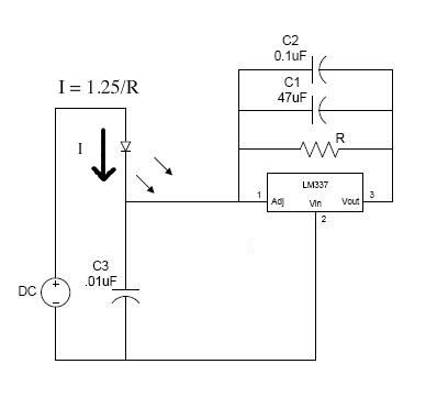
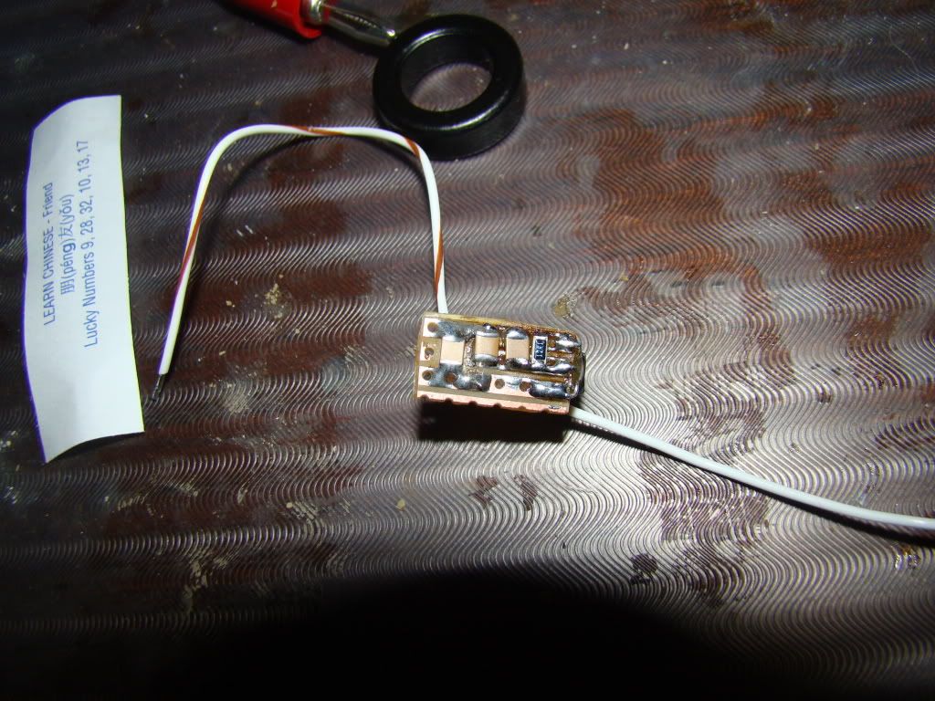
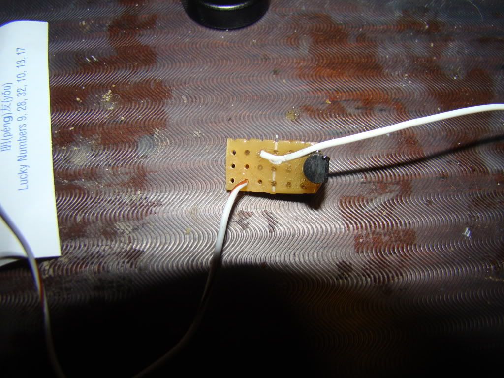
So I made my own PCB according to the diagram I double and triple checked
everything :
B+ to case
B- to Adj pin and cap's negative
Vin to diode's negative and cap's negative
I set the current to nearly 380mA. ..~370mA something
I connected the test load, connected the adjustable power supply,
pushed the button and now comes the funny stuff

when I was cranking up the voltage from 0V to 6V i got a steady current
going up! Good for now.. at 6V I got to the 370mA.. So I started cheering ..
then I turned the voltage up and WHOA?! the current suddenly dropped to
250mA and stayed there no matter how many volts I fed it with....
when I returned to 6V input I got my 370mA current again...
so I decided to see how does it behave on my 150mW IR diode..
it's maximum current is 380mA.. and I have set it to almost there..
now I stared from 0V again and when I reached 4.7V the current
was 370mA so I decided to stop cranking the voltage up and see what
happens next..
at some moments later what I saw was that the current was slowly
starting to rise due to heat... the hotter the diode and driver got the
more current was going in.. from 370mA it went to 380mA and I turned it off..
don't want to kill my diode

because if had crossed the border of regulation... I think it's not regulating
properly when connected after the diode... I don't know how it turned out
for you guys but for me it didn't work.. maybe LM317 behaves differently in
this manner but my LM1117 doesn't... :gun::cryyy:
well I just wanted to share that with you ... if you have any suggestions or thoughts pls share

I am going to get some sleep now ... it's almost 4am ..... goodnight :can:
p.S. I guess that's why there are negative rail regulators and positive rail regulators and not just
ONE of them if it worked both ways don't you think??


I think this was doomed from the beginning ...


