

IgorT
0
- Joined
- Oct 24, 2007
- Messages
- 4,177
- Points
- 0
Since i often have to test large batches of diodes to sort them by efficiency, i was preparing an improoved method of plotting them, which would allow for a better comparison of diodes of the same type, and also allow comparing completelly different diodes, be it a different model or even a different wavelength..
I also wanted to compare Reds to BluRays in a meaningful way, something that is not possible with the usual PI or PIV plots..
For now i tried comparing a high efficiency 8x and a high efficiency LOC - something i've been meaning to do for a while, especially since BluRay diodes are suddenly reaching powers higher than even the toughest Reds..
I found the results quite interesting, and thought they deserved their own thread, so here goes...
Until now we have mostly been using the slope efficiency plots (mW per mA) to compare one diode to another...
Slope efficiency comparison is often enough, but diodes vary in their forward voltage even among the same model. The variations in Vf can be even greater between diodes from different manufacturers, while different wavelength diodes work in completelly different voltage ranges.. And Vf matters a lot, when it comes to actual diode efficiency!
For example:
- If one diode produces less power at a certain current, but has a substantially lower forward voltage, it could actually be more efficient than a diode that produces more power at that current but with a much higher Vf...
- If two diodes produce the same power at the same current, but one of them has a lower Vf, that diode is in reality more efficient, and will produce less heat at that current..
When testing 6x's, i found the Vfs to vary quite a bit, and because of that, i wanted to use a more accurate method for comparing 8x's.. I would still make the usual slope efficiency plots (mW per mA), but for a proper comparison, i'd use Po vs. Pe plots (Optical Power OUT vs. Electrical Power IN)...
Since the differences are small among diodes of the same type, i wanted to demonstrate the importance of Vf by comparing an 8x to a LOC...
I started by collecting the data and plotting it in the usual way.
In every plot i used:
- a red line for the LOC's primary axis (showing output power (Po) in all graps)
- a dark blue line for the 8x's primary axis (as above - optical power (Po) in all graphs)
- a pink line for the LOC's secondary axis (showing either Vf, Efficiency, El. Power (Pe), or Heat)
- a light blue line for the 8x's secondary axis (as above - depending on the graph)
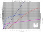
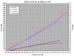
- Plot #1 is a normal PIV plot of an 8x and a LOC
It shows all the electrical characteristics of each diode. It has a meaning for each of the two individually, but for comparing them it is (almost) completelly useless.. All it shows is that the Vf of an 8x is much higher than that of a LOC, and that the LOC needs WAY more current to even start lasing..

Since the two diodes are plotted by the input current, the two plots stand very far appart. The 8x seems MUCH more efficient than the LOC, since it produces so much more power at the same input currents.
But it's much higher Vf shows that in reality, the electrical power into the 8x diode is a lot higher at the same currents than with the LOC...
Next i made a new plot, where the optical output power of each diode is plotted against it's input power..
- Plot #2 is a Po/Pe & Efficiency plot
It shows Optical Output Power plotted against Electrical Input Power for both diodes, as well as their ACTUAL efficiency (a percentage showing how much of the electrical input power is converted into optical output power)..

The plot still consists of the same data as the first one, except that here i multiplied the input current (I) and forward voltage (Vf) data for each diode, to get the electrical input power (Pe), and plotted their output powers (Po) against the results. Instead of the current, the X axis shows the electrical power into the diode.. Since i now had both the input and the output powers, i could also calculate actual efficiency of each diode and plot that onto the secondary Y axis...
Because they are plotted against el. input power, the two plots now stand much closer together, and for a while, the diodes exhibit significant similarities, and at the same time the actual differences start becoming apparent...
The new plot shows that the open can needs more electrical power to start lasing, but the difference is not even nearly as big as the first plot seemed to suggest.. The plot also shows, that for a while the slope of the LOC is steeper than that of the 8x.. The open can almost wants to exceed the 8x in efficiency (if this was a low efficiency 8x, the open can would exceed itfor a while).
But then it starts falling into the knee all reds are limited by. The power of the LOC starts increasing less and less, the further i go - every next increase in input power results in a lower increase in output power and a higher increase in heat dissipation. This is even more noticable in it's efficiency plot, which starts dropping rapidly after the peak.
BluRays on the other hand don't have these knees, and simply continue upwards in a straight line. Every increase in input power results in the same increase in the output power. Well, almost the same. The power line looks almost straight, but the efficiency line does show a drop.
In the case of BluRay diodes however, this efficiency drop is not the result of a knee or anything similar, but rather the result of the heat that developed during plotting.
If the temperature of the 8x diode was kept constant throughout the testing, the power really would form a straight line, and the efficiency plot would be horizontal after the peak...
Some interesting things i've noticed so far:
- With reds (i plotted LOCs and LCCs) the Vf climbs linearly as the current is increased - the diode's forward voltage increases by the same amount with each step of current increase - the Vf plot is a straight line... But their output power line starts curving down more and more.
- With BluRays it is the other way around! The Vf line starts curving down more and more as the current is increased, while their output power keeps climbing linearly.. Each step of current increase brings the same amount of power increase - their efficiency is only affected by their own heat..
The two diodes are behaving in the opposite way!
This might also provide a small clue as to where the knee comes from with reds, and why BluRays can be overdriven to such bizzare levels..
Since the electrical input power is a factor of current and voltage (P = U x I), and with reds, voltage increases linearly with current, this means that the electrical power going into the diode is increasing exponentially, as the current is raised! If i were to plot input power against input current, the plot would form an upwards bending curve..
But with BluRays, every next current increase results in a smaller voltage increase. It looks like the Vf increase is dropping just enough with each step, so that the input power increase stays the same with every step in current!
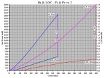
To check this, i made (yet) another plot..
- Plot #3 shows El. Input Power (Pin) & Opt. Output Power (Pout) plotted against Current...

As predicted, i get a straight line for the 8x and an upwards bending curve for the LOC..
This means, that as the current into a BluRay diode is increased, the input AND output powers both increase linearly with every step!
But with a Red the input power increase grows exponentially, while the output power increase drops exponentially with every step, until it gets to a point, where the output power no longer increases, and a current increase only results in more heat created...
The third graph also shows something else. The optical output power is plotted against the left Y axis in mW. The electrical input power is plotted against the right Y axis in W. In this case i put both the left and the right Y axis into the same scale - they both end at 2.4W...
Because of this, if you draw a vertical line from the diodes el. input power to it's optical output power, the length of that line directly corresponds to the amount of heat created at that current (= difference between input and output power).. I drew such a line at the highest current each diode was pushed to... With the red you can see it outputs 0.4W, when it's being fed 2.4W, meaning it is creating 2W of heat...
(This is also why in this plot i wrote Pin for Pe and Pout for Po, because the difference between the power going in and power coming out is Thermal Power, or HEAT, since it's impossible for less power to come out than goes in...)
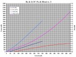
And since i was thinking about heat now, i made a fourth plot...
- Plot #4 shows Output Power & Heat vs. Current
Here i wanted to show how heat grows exponentially with reds, and to show this, i had to plot it against current.. If i plotted it against input power, the curvature would not be this obvious, since input power already grows exponentially with reds.

It also shows that with a BluRay the heat grows linearly with input current (as mentioned before, the slight but noticable curvature is a result of the diode not being kept at a constant temperature)...
This graph is not that much different from the previous one, the bottom two lines are the same as before, but the top two now show the calculated heat - the difference between the input and the output power i was talking about while describing the previous plot...
For the last plot, i again wanted to show the two diodes in a way they could be compared better, so i repeated the previous plot, but this time i used input power - Pe (or Pin) - for the X axis...
- Plot #5 shows Output Power & Heat vs. El. Input Power
This plot is again much better suited to compare different diodes, because the data is plotted against input power on the X axis...

Now the lines are suddenly so close together, that the two diodes almost seem to display more similarities than differences.. But only until you realize, that it's the outer two lines that represent the LOC, and the inner two lines that represent the 8x! And the LOC lines are curving appart, while the 8x's lines are straight (again)..
While i have the feeling i've been repeating myself for a while now, i want to show something interesting on this last plot:
- Let's start with the LOC... If you look at the plot, it takes 1.3W of el. input power, to reach 300mW of output power. And at this same point the LOC produces 1W of heat (just go up from 1.3W first to the red line and then to the pink one).
- The 8x on the other hand reaches 300mW at 1.15W of input power, and produces 0.875W of heat, judging by the graph (i used a higher resolution graph to get to these numbers, cos i don't have exact numbers for that specific power recorded)....
So far, while there is a difference, it is relativelly low, but it's clear that the 8x is quite a bit more efficient.
But let's say i want 400mW!
- To reach 400mW with the LOC, i have to feed it 2.4W of electrical power, and at that point it produces 2W of heat! I only reached 33.3% more power than before, but the diode is producing TWICE AS MUCH HEAT as it did at 300mW!
- Now let's look at the 8x... It reaches 400mW at 1.56W input power, and produces only 1.16W of heat! Again a 33.3% power increase, but the heat doesn't seem to have increased all that much!
Let's calculate how much the heat increased (or does anyone want to guess?).. 1.16 - 0.875 = 0.285W => 0.285 / 0.875 * 100 = 32.6% more heat...
I would have guessed 33.3%, because as i mentioned multiple times in this post, every aspect of the 8x except it's Vf behaves linearly.. The reason the calculation was off is that i didn't have measured numbers for 300 and 400mW, but had to read the values off the plot. Considering this, the error is quite small...
I could now also try to calculate how much more input power it took to go from 300 to 400mW with the 8x, but again i'd be more accurate if i simply said 33.3% more input power, or rather one third more...
So with an 8x, to increase the power by one third, the input power has to be increased by one third, and the amount of heat produced will increase by one third.
With a LOC, it takes 84.6% (2.4 - 1.3 = 1.1 => 1.1 / 1.3 x 100 = 84.6%) more input power, to reach one third more output power, and the poor diode creates TWICE as much heat!
"Conclusion":
It's no wonder reds can only be pushed so far.... You're probably wondering since the very first graph, how i was even able to plot a LOC to 640mA! The only reason i was able to do it is that i was increasing the current slowly, by hand, on my Diode Analyzer.... In a laser, where this current comes on suddenly at power-up, the diode unforunatelly dies instantly.
I tried it several times, on the Diode Analyzer i could bring them to 640mA every single time, in a laser they would pop instantly. I repeated this over and over again, until i had a mixture of six or seven dead LOC's and LCC's...
The only reason i even tried going so far is that i saw a post showing a 510mW LOC laser - the result of a freak accident.. I was trying to replicate the result, but no luck... I did gather a lot of interesting data however...
One thing i forgot to mention... This particular LOC seems to exhibit something resembling a kink, most noticable in the first two plots. Especialy in the second one, the efficiency line also displays a sudden drop. Unfortunatelly i did not plot the other open cans i killed - i just tried to see if they can survive 620-640mA..
I did plot an LCC tho, and it does not show anything like that.. It's plot is a smooth curve. I don't know if this was a weird LOC or if others have it, i'll have to test a couple more. But i think it's an exception...
In any case these plots make it a little easier to understand why BluRays can be overdriven to such bizzare levels, but much more than that, it shows why reds can't!
One thing's for sure, 405nm's are weird diodes! But that's nothing new, i've been saying it for over a year now..
But these comparisons did give me a slightly better insight into their behavior.
I just hope i'm not the only one obsessed enough to find all this interesting... :yabbem:
P.S. I've been thinking a lot about the fact, that the reds survived (or rather didn't die instantly) when i raised the current slowly, even if i tried repeating it, but died every single time, when i put them on a FlexDrive set to the same current...
If a driver was made to raise the current VERY slowly at powerup, one could make a 400mW+ red that would light up at least a few times.. Of course it would ultimatelly still die quite rapidly, because the amounts of electrical power going in and heat being created are beyond bizzare....
But still, a very slow powerup allowed me to bring reds to 400mW several times, while an instant powerup killed them on the spot!
If it makes such a big difference here, it would surelly also make a difference at the currents they can survive..
It is well known, that it's the power-up stresses that torture diodes the most, and they often die just when you turn them ON..
I can't help but wonder how much longer diodes could live if they were powered by a driver that would raise the current so slowly, you could actually see the power gently climbing to max..
I'm thinking of performing another test on the Cycler, killing several cheap diodes (PHRs and reds), half of them powered by a regular driver and the other half powered by a very gentle slow power-up driver, to see HOW MUCH of a difference it could make at "normal" currents...
I also wanted to compare Reds to BluRays in a meaningful way, something that is not possible with the usual PI or PIV plots..
For now i tried comparing a high efficiency 8x and a high efficiency LOC - something i've been meaning to do for a while, especially since BluRay diodes are suddenly reaching powers higher than even the toughest Reds..
I found the results quite interesting, and thought they deserved their own thread, so here goes...
***
Until now we have mostly been using the slope efficiency plots (mW per mA) to compare one diode to another...
Slope efficiency comparison is often enough, but diodes vary in their forward voltage even among the same model. The variations in Vf can be even greater between diodes from different manufacturers, while different wavelength diodes work in completelly different voltage ranges.. And Vf matters a lot, when it comes to actual diode efficiency!
For example:
- If one diode produces less power at a certain current, but has a substantially lower forward voltage, it could actually be more efficient than a diode that produces more power at that current but with a much higher Vf...
- If two diodes produce the same power at the same current, but one of them has a lower Vf, that diode is in reality more efficient, and will produce less heat at that current..
When testing 6x's, i found the Vfs to vary quite a bit, and because of that, i wanted to use a more accurate method for comparing 8x's.. I would still make the usual slope efficiency plots (mW per mA), but for a proper comparison, i'd use Po vs. Pe plots (Optical Power OUT vs. Electrical Power IN)...
Since the differences are small among diodes of the same type, i wanted to demonstrate the importance of Vf by comparing an 8x to a LOC...
I started by collecting the data and plotting it in the usual way.
In every plot i used:
- a red line for the LOC's primary axis (showing output power (Po) in all graps)
- a dark blue line for the 8x's primary axis (as above - optical power (Po) in all graphs)
- a pink line for the LOC's secondary axis (showing either Vf, Efficiency, El. Power (Pe), or Heat)
- a light blue line for the 8x's secondary axis (as above - depending on the graph)
- Plot #1 is a normal PIV plot of an 8x and a LOC
It shows all the electrical characteristics of each diode. It has a meaning for each of the two individually, but for comparing them it is (almost) completelly useless.. All it shows is that the Vf of an 8x is much higher than that of a LOC, and that the LOC needs WAY more current to even start lasing..
Since the two diodes are plotted by the input current, the two plots stand very far appart. The 8x seems MUCH more efficient than the LOC, since it produces so much more power at the same input currents.
But it's much higher Vf shows that in reality, the electrical power into the 8x diode is a lot higher at the same currents than with the LOC...
Next i made a new plot, where the optical output power of each diode is plotted against it's input power..
- Plot #2 is a Po/Pe & Efficiency plot
It shows Optical Output Power plotted against Electrical Input Power for both diodes, as well as their ACTUAL efficiency (a percentage showing how much of the electrical input power is converted into optical output power)..
The plot still consists of the same data as the first one, except that here i multiplied the input current (I) and forward voltage (Vf) data for each diode, to get the electrical input power (Pe), and plotted their output powers (Po) against the results. Instead of the current, the X axis shows the electrical power into the diode.. Since i now had both the input and the output powers, i could also calculate actual efficiency of each diode and plot that onto the secondary Y axis...
Because they are plotted against el. input power, the two plots now stand much closer together, and for a while, the diodes exhibit significant similarities, and at the same time the actual differences start becoming apparent...
The new plot shows that the open can needs more electrical power to start lasing, but the difference is not even nearly as big as the first plot seemed to suggest.. The plot also shows, that for a while the slope of the LOC is steeper than that of the 8x.. The open can almost wants to exceed the 8x in efficiency (if this was a low efficiency 8x, the open can would exceed itfor a while).
But then it starts falling into the knee all reds are limited by. The power of the LOC starts increasing less and less, the further i go - every next increase in input power results in a lower increase in output power and a higher increase in heat dissipation. This is even more noticable in it's efficiency plot, which starts dropping rapidly after the peak.
BluRays on the other hand don't have these knees, and simply continue upwards in a straight line. Every increase in input power results in the same increase in the output power. Well, almost the same. The power line looks almost straight, but the efficiency line does show a drop.
In the case of BluRay diodes however, this efficiency drop is not the result of a knee or anything similar, but rather the result of the heat that developed during plotting.
If the temperature of the 8x diode was kept constant throughout the testing, the power really would form a straight line, and the efficiency plot would be horizontal after the peak...
Some interesting things i've noticed so far:
- With reds (i plotted LOCs and LCCs) the Vf climbs linearly as the current is increased - the diode's forward voltage increases by the same amount with each step of current increase - the Vf plot is a straight line... But their output power line starts curving down more and more.
- With BluRays it is the other way around! The Vf line starts curving down more and more as the current is increased, while their output power keeps climbing linearly.. Each step of current increase brings the same amount of power increase - their efficiency is only affected by their own heat..
The two diodes are behaving in the opposite way!
This might also provide a small clue as to where the knee comes from with reds, and why BluRays can be overdriven to such bizzare levels..
Since the electrical input power is a factor of current and voltage (P = U x I), and with reds, voltage increases linearly with current, this means that the electrical power going into the diode is increasing exponentially, as the current is raised! If i were to plot input power against input current, the plot would form an upwards bending curve..
But with BluRays, every next current increase results in a smaller voltage increase. It looks like the Vf increase is dropping just enough with each step, so that the input power increase stays the same with every step in current!
To check this, i made (yet) another plot..
- Plot #3 shows El. Input Power (Pin) & Opt. Output Power (Pout) plotted against Current...
As predicted, i get a straight line for the 8x and an upwards bending curve for the LOC..
This means, that as the current into a BluRay diode is increased, the input AND output powers both increase linearly with every step!
But with a Red the input power increase grows exponentially, while the output power increase drops exponentially with every step, until it gets to a point, where the output power no longer increases, and a current increase only results in more heat created...
The third graph also shows something else. The optical output power is plotted against the left Y axis in mW. The electrical input power is plotted against the right Y axis in W. In this case i put both the left and the right Y axis into the same scale - they both end at 2.4W...
Because of this, if you draw a vertical line from the diodes el. input power to it's optical output power, the length of that line directly corresponds to the amount of heat created at that current (= difference between input and output power).. I drew such a line at the highest current each diode was pushed to... With the red you can see it outputs 0.4W, when it's being fed 2.4W, meaning it is creating 2W of heat...
(This is also why in this plot i wrote Pin for Pe and Pout for Po, because the difference between the power going in and power coming out is Thermal Power, or HEAT, since it's impossible for less power to come out than goes in...)
And since i was thinking about heat now, i made a fourth plot...
- Plot #4 shows Output Power & Heat vs. Current
Here i wanted to show how heat grows exponentially with reds, and to show this, i had to plot it against current.. If i plotted it against input power, the curvature would not be this obvious, since input power already grows exponentially with reds.
It also shows that with a BluRay the heat grows linearly with input current (as mentioned before, the slight but noticable curvature is a result of the diode not being kept at a constant temperature)...
This graph is not that much different from the previous one, the bottom two lines are the same as before, but the top two now show the calculated heat - the difference between the input and the output power i was talking about while describing the previous plot...
For the last plot, i again wanted to show the two diodes in a way they could be compared better, so i repeated the previous plot, but this time i used input power - Pe (or Pin) - for the X axis...
- Plot #5 shows Output Power & Heat vs. El. Input Power
This plot is again much better suited to compare different diodes, because the data is plotted against input power on the X axis...
Now the lines are suddenly so close together, that the two diodes almost seem to display more similarities than differences.. But only until you realize, that it's the outer two lines that represent the LOC, and the inner two lines that represent the 8x! And the LOC lines are curving appart, while the 8x's lines are straight (again)..
While i have the feeling i've been repeating myself for a while now, i want to show something interesting on this last plot:
- Let's start with the LOC... If you look at the plot, it takes 1.3W of el. input power, to reach 300mW of output power. And at this same point the LOC produces 1W of heat (just go up from 1.3W first to the red line and then to the pink one).
- The 8x on the other hand reaches 300mW at 1.15W of input power, and produces 0.875W of heat, judging by the graph (i used a higher resolution graph to get to these numbers, cos i don't have exact numbers for that specific power recorded)....
So far, while there is a difference, it is relativelly low, but it's clear that the 8x is quite a bit more efficient.
But let's say i want 400mW!
- To reach 400mW with the LOC, i have to feed it 2.4W of electrical power, and at that point it produces 2W of heat! I only reached 33.3% more power than before, but the diode is producing TWICE AS MUCH HEAT as it did at 300mW!
- Now let's look at the 8x... It reaches 400mW at 1.56W input power, and produces only 1.16W of heat! Again a 33.3% power increase, but the heat doesn't seem to have increased all that much!
Let's calculate how much the heat increased (or does anyone want to guess?).. 1.16 - 0.875 = 0.285W => 0.285 / 0.875 * 100 = 32.6% more heat...
I would have guessed 33.3%, because as i mentioned multiple times in this post, every aspect of the 8x except it's Vf behaves linearly.. The reason the calculation was off is that i didn't have measured numbers for 300 and 400mW, but had to read the values off the plot. Considering this, the error is quite small...
I could now also try to calculate how much more input power it took to go from 300 to 400mW with the 8x, but again i'd be more accurate if i simply said 33.3% more input power, or rather one third more...
So with an 8x, to increase the power by one third, the input power has to be increased by one third, and the amount of heat produced will increase by one third.
With a LOC, it takes 84.6% (2.4 - 1.3 = 1.1 => 1.1 / 1.3 x 100 = 84.6%) more input power, to reach one third more output power, and the poor diode creates TWICE as much heat!
"Conclusion":
It's no wonder reds can only be pushed so far.... You're probably wondering since the very first graph, how i was even able to plot a LOC to 640mA! The only reason i was able to do it is that i was increasing the current slowly, by hand, on my Diode Analyzer.... In a laser, where this current comes on suddenly at power-up, the diode unforunatelly dies instantly.
I tried it several times, on the Diode Analyzer i could bring them to 640mA every single time, in a laser they would pop instantly. I repeated this over and over again, until i had a mixture of six or seven dead LOC's and LCC's...
The only reason i even tried going so far is that i saw a post showing a 510mW LOC laser - the result of a freak accident.. I was trying to replicate the result, but no luck... I did gather a lot of interesting data however...
One thing i forgot to mention... This particular LOC seems to exhibit something resembling a kink, most noticable in the first two plots. Especialy in the second one, the efficiency line also displays a sudden drop. Unfortunatelly i did not plot the other open cans i killed - i just tried to see if they can survive 620-640mA..
I did plot an LCC tho, and it does not show anything like that.. It's plot is a smooth curve. I don't know if this was a weird LOC or if others have it, i'll have to test a couple more. But i think it's an exception...
In any case these plots make it a little easier to understand why BluRays can be overdriven to such bizzare levels, but much more than that, it shows why reds can't!
One thing's for sure, 405nm's are weird diodes! But that's nothing new, i've been saying it for over a year now..
But these comparisons did give me a slightly better insight into their behavior.
I just hope i'm not the only one obsessed enough to find all this interesting... :yabbem:
P.S. I've been thinking a lot about the fact, that the reds survived (or rather didn't die instantly) when i raised the current slowly, even if i tried repeating it, but died every single time, when i put them on a FlexDrive set to the same current...
If a driver was made to raise the current VERY slowly at powerup, one could make a 400mW+ red that would light up at least a few times.. Of course it would ultimatelly still die quite rapidly, because the amounts of electrical power going in and heat being created are beyond bizzare....
But still, a very slow powerup allowed me to bring reds to 400mW several times, while an instant powerup killed them on the spot!
If it makes such a big difference here, it would surelly also make a difference at the currents they can survive..
It is well known, that it's the power-up stresses that torture diodes the most, and they often die just when you turn them ON..
I can't help but wonder how much longer diodes could live if they were powered by a driver that would raise the current so slowly, you could actually see the power gently climbing to max..
I'm thinking of performing another test on the Cycler, killing several cheap diodes (PHRs and reds), half of them powered by a regular driver and the other half powered by a very gentle slow power-up driver, to see HOW MUCH of a difference it could make at "normal" currents...


")