Welcome to Laser Pointer Forums - discuss green laser pointers, blue laser pointers, and all types of lasers

Buy Site Supporter Role (remove some ads) | LPF Donations

Links below open in new window

ArcticMyst Security by Avery | Browser Hide by Avery

Blue laser 74W NUBM35 Portabl?

I understood you. I didn't know that, about the input voltage that it should be lower than the output voltage. I will be careful when trying. I will use two 6 battery power supplies as you say. 👍


I have watched videos with a test of this current amplifier and it behaves very stable. It would definitely manage to power all 14 diodes at once with 12 batteries. But I think that with two drivers is the best option, because I will be able to include each line separately or all together.
Can't wait for things to arrive 😀

1200W 20A DC Converter Boost Step-up Power Supply Module IN 8-60V OUT 12-83V
 

Attachments

  • 1115409662-681758671.jpg
    1115409662-681758671.jpg
    180.3 KB · Views: 5
That's a 1200W 20A but the last one you linked was 600W 10A, either one will work for all 14 diodes needing 4.5V @ 5A which is only 315W.

However as the upper operating limit of either model of driver is 60V and all 14 diodes would need 63V plus fractions of a volt each and resistive losses, I think your using one driver for each string of 7 diodes is better, that way you will only need 31.5V and as we discussed 6 x 18650 will input safely at least 2V less than your output.

Driving your laser array @ 5A with 6 cells each battery will need to output something like 7A which is perfectly reasonable for good quality cells and short duty cycles.......actually you could use a 7 x 18650 battery pack but 8 x 18650 would be too many, now you could put 2 packs of cells in parallel but that's getting bulky again.......actually you could use your 2 packs in parallel to supply both drivers with each pack containing 6 cells in series and then switch on either one string of 7 laser diodes or both strings, that way both packs share the load when running 1 string, you could add a 3rd pack containing 6 cells in series if needed later for longer runtime or use 3 of the 4S hobby packs in parallel as a common bank for both drivers again switching on one or both laser diode strings. Also this will prevent one pack running down before the other when running only 1 string of 7.

7 laser diodes needing 4.5V @ 5A is 157.5W and 6 battery cells @ 4V putting out 7A is 168W which is about right as the boosting drivers are usually 95% efficient 168W x 0.95 = 159.6 so yea, about 7A but it will be less when you drive the array @ 3.5A however as your cells discharge the current draw will be a little higher.

p.s. The 1200W driver is good for 83V output where as the 600W unit was only 60V output, so you could use the 1200W unit to drive all 14 laser diodes in series if you wanted to and maybe use 3 of the 4S hobby packs in parallel for ease of recharging, you may want a common battery pack in series/parallel using the hobby packs for easy recharging if you use 1 driver or 2 anyway.
 
Last edited:
Thanks a lot for the comprehensive answer. I won't buy the 1200w one. I just gave it as an example. I'm going to use two drivers because I think it's best. And the power supply with the batteries will be, as I judge, 2x6 in parallel or 2x6 to each driver. I know a guy from Romania and he told me that he used this 400w driver for many things and it was very stable. I have purchased both so will be testing both. I wanted to ask something else. Because these drivers come with factory settings of Voltage and Amperage. I want to use some power sink to pre-set the drivers to 4A. In the sense that it is not a direct test on the laser array, so as not to damage it if they are accidentally set above 6A
 
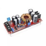
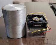
You can use 5 automotive light bulbs in series as the driver will arrive set at 50V, connect your load ( 5 bulbs in series ) then your battery, turn both pots all the way down, I like to use an inductive ammeter, you can test the driver with the light bulbs to get a feel for how it works.

You want to turn the pots all the way down before connecting to your laser array, then using an inductive amp meter adjust both pots up slowly ( while connected to the array ) slowly, one just a little until the brightness won't increase, then the other just a little until the brightness wont increase and then once you reach the 3.5A or whatever your target current, then turn the current pot back until you see the reading move down, then back up until your target, then turn the volts back gently until you see the amp reading just start to move down, you will have both pots set.

p.s. Note: Don't power up the driver without a load connected.
 
Last edited:
@RedCowboy
I chose what the body would be. This electrical box. I think it will fit everything inside, even 12 batteries. I will mount a handle on top. I'm torn on what to use for cooling. The radiator with a fan, which will rest on an aluminum radiator with dimensions 100x60x10mm or the aluminum array, but without a fan.
I also bought temperature sensors that I will install on the radiator. If it exceeds 70C they will disconnect. I think it's better to have them.

I also found a suitable charger 24V/2A that will manage to charge 6 pieces of 18650. This makes it a lot easier for me because everything will stay inside without having to remove all the batteries every time

6S 15A 24V PCB BMS Protection Board for 6 Pack 18650 Li-ion Lithium Battery Cell Module DIY Kit
 

Attachments

  • Screenshot_20221209_162634_com.android.gallery3d_edit_610941386498963.jpg
    Screenshot_20221209_162634_com.android.gallery3d_edit_610941386498963.jpg
    343.2 KB · Views: 5
  • Screenshot_20221209_162621.jpg
    Screenshot_20221209_162621.jpg
    827.2 KB · Views: 2
  • Screenshot_20221209_162616_com.android.gallery3d.jpg
    Screenshot_20221209_162616_com.android.gallery3d.jpg
    984.4 KB · Views: 5
  • Screenshot_20221209_162600_edit_611257948328081.jpg
    Screenshot_20221209_162600_edit_611257948328081.jpg
    579.7 KB · Views: 5
  • Screenshot_20221209_163437.jpg
    Screenshot_20221209_163437.jpg
    897.2 KB · Views: 6
  • 25222005951878749.jpg
    25222005951878749.jpg
    379 KB · Views: 4
  • -561971884-979730745.jpg
    -561971884-979730745.jpg
    219.4 KB · Views: 4
Last edited:
Nice but I discovered the normal spring type battery holders needed to be reinforced as they got hot at the contacts and went open.
These flat spring contact type work much better. They come in 1,2,3,4 cell holders so you can build a pack whatever size you want.


@RedCowboy
I bought the same ones as in the second link
 

Attachments

  • 14773751462057791524.jpg
    14773751462057791524.jpg
    214.2 KB · Views: 2
  • -2116902989-1576781757.jpg
    -2116902989-1576781757.jpg
    109.5 KB · Views: 2
I have ordered from these as well
 

Attachments

  • 2131396193578389061.jpg
    2131396193578389061.jpg
    217 KB · Views: 2
If you build a multi cell pack with those braces and solder tabs across the tops/bottoms then you will have to recharge the entire pack at a higher voltage which you can do with one of those DC-DC converters, but I believe the smart chargers sense the charge rate and adjust, so I like the springed holders that way each cell can be recharged and when needed replaced.
 
And which of the two do you think is the best option to cool?
 

Attachments

  • Screenshot_20221209_163437.jpg
    Screenshot_20221209_163437.jpg
    897.2 KB · Views: 2
The fan over finned sink is the way to go, I'm sure you know that you need to use a little thermal grease between the array and the sink to get good heat transfer.

Also while you're working with the array, before you set up a final optics solution, using even a very simple shroud helps block a lot of lens flair and cleans up your beam bundle.
As you can see even in these poor quality pics, a simple cardboard tube blocks a lot of flair.
 

Attachments

  • SANY6682.JPG
    SANY6682.JPG
    183.7 KB · Views: 9
  • SANY6685.JPG
    SANY6685.JPG
    171.5 KB · Views: 6
  • SANY6690.JPG
    SANY6690.JPG
    161.4 KB · Views: 9
  • SANY6693.JPG
    SANY6693.JPG
    183.6 KB · Views: 9
Last edited:
Thermal paste will be mandatory. He can't do without her. Well, there will remain an option for a hood in the front to stop the reflection of the side light
 
@RedCowboy
I'm thinking of making a battery like this with this charger attached to charge with a 24V adapter. However, will there be a problem if I connect the two drivers in parallel to it? I'm doing it because that way I can charge all 12 batteries together instead of two separate 6 battery packs. The rest remains the same, each driver will power 7pcs diodes

 
25.2 volts is just fine, you will be wiring your 12 cells in series-parallel just like in the video correct ? Basically you are making 6 double cells and then connecting your 6 double cells in series 25.2V fully charged.

The reason he parallels each pair then wires them in series, rather than making 2 strings of 6 and then paralleling the two strings is because of how the charger works, so make your connections just like in the video.
Yes, I will do exactly the same as in the video. My question was if it would be a problem to power both drivers at the same time from the 12 cell 25V battery made.


Back
Top