Welcome to Laser Pointer Forums - discuss green laser pointers, blue laser pointers, and all types of lasers

LPF Donation via Stripe | LPF Donation - Other Methods

Links below open in new window

ArcticMyst Security by Avery

8X Diode Murder fund

IgorT

0
Joined
Oct 24, 2007
Messages
4,177
Points
0
If you want to test at the same power as the 1st 8X diode,
that would be 260ma (from graph) x 150% or 390ma.

For the 1st long 12X test procedure, it probably should not be an extreme overdrive.

I believe we should go by power, not current - if we try to calculate how far to push the 12x in relation to one or the other 8x diode...

The first 8x diode was pushed to 2.848x and the second one to 3.624x their rated CW power.
For a 12x, that would be 427.2mW or 543.6mW, regardles of what current would be required to reach it..

If 12x's have the same toughnes as 8x's only at a higher power, that would mean they could survive 427mW for over 340 hours and 544mW for around 200 hours (+/- ?).


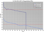
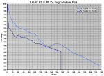
After observing the degradation of three 8x diodes, i am becoming convinced, that the determining factor for diode life is the power setting and not the current required to reach it.


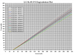
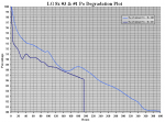
On the right side of the attachment below, you can see the murder of multiple diodes, which each required a different current to reach 320mW Pulsed, due to their varying efficiency. And yet the lines are pretty much parallel, indicating that regardless of the current required, the diodes degrade at almost the same rate when set to the same power...

The 60mW Sanyo diode lifetime/degradation chart indicated the same thing as well..


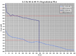
This is a graph from Nichia on 320mw 12X BR diodes:
fig6.jpg


P.S. Nichia did their life test 30 second intervals at 320mw power for 1000 hours.
Almost comparable to your first test procedure of over 320 hours, when you add the 80° C temp factor.

I am fairly certain, that the 30s in the above attachment is a typo.

They are talking about pulse oscillation with a 50% duty cycle, where the pulsewidth is specified as 30ns in almost every datasheet i've seen.


Also, 1000h is one of their standards of reliability for disk writer drives (the minimum). I don't think the diode could have survived as long with 30 second CW cycles (30s is not really a pulse)...


If it's not a typo, then that's one tough diode, altho why would they test them using their estimated diode working temperature inside a drive (80°C), if the test was completelly unrelated to this application?


It doesn't make sense, it must be a typo. I'm so used to reading 50% duty cycle / 30ns pulse-width, that i when i first read it, i read nanoseconds and not seconds.
 
Last edited:


Joined
Dec 6, 2008
Messages
1,581
Points
63
Igor;

I have seen the above test protocol in 2 different releases from Nichia.

The 2nd one said 1000 hours @ 80° C,
predicted 10,000 hours at normal operating levels.

I do think that power output is a key factor,
but all the drivers we use have to be set for current initially.

At 150% of Peak Power,
that would be 480mw for a "320mw" peak power diode.

I also think that your test bench got longer operating hours due to the better heatsinks.

LarryDFW
 
Last edited:

IgorT

0
Joined
Oct 24, 2007
Messages
4,177
Points
0
Of course mine could just be positive mental imagery as well ;)

I'm hoping when it gets hooked up again, that we will still learn something from it.

Peace,
dave


Actually, the first 12x is DEAD. It's not just degraded, it's properly dead.

But at the same time it is still LASING!!!! It's UNdead - a zombie diode! I locked it away, so it wouldn't eat the dies of other diodes and turn them into zombies too!


It can't be classified as alive and just degraded, because... Well.. While it's still "LASING", it's not lasing from a tiny point source with the proper shape as it should. It's as if it was lasing from a larger rounder area, with dark gaphs in between forming that evil zombie smiley face i posted.

I don't know what - if anything - i can still do with it. It's busted.

This is the only diode where i would even consider a "push it till it pops" test. Even with the horrible damage it might still be able to point out where a 12x might give up "instantly". Or maybe not, due to the extensive pre-existing damage.


The really bizzare part is the power it produces... I've seen DEAD BDR-"S03s" lase after dying, but only a few mW.
This thing is undead, because it produces 360mW at 420mA!

But the beam it produces is PERFECTLLY ROUND with "holes" in it, very noticable in smoke. It's really strange to see a dead diode burning stuff!


In any case, i've never seen anything like it before. We've had zombie-PHRs a long time ago, but it was nothing like this! I'm completelly baffled.
 
Last edited:

IgorT

0
Joined
Oct 24, 2007
Messages
4,177
Points
0
I do think that power output is a key factor,
but all the drivers we use have to be set for current initially.

Of course we have to set them to a certain current, what i'm saying is, that instead of testing a current, we should be testing a power, and simply set the current accordingly - to reach the power we decide to test.

For example with the 8x's, i decided the first current to test should be 300mA. I thought a lower efficiency diode is weaker than higher efficiency ones, and that a 300mA test of a low efficiency diode would show the minimum 8x's survive at 300mA.

But after getting so many hours, and seeing a higher efficiency diode degrade much faster, i started realizing, that we didn't really test the safety of 300mA, but the safety of 356mW instead. I believe the first diode should have been pushed to 400mW regardless of the current it would take, because the result would be closer to what the other 8x's can survive at 400mW than what they can survive at 300mA.

I believe (or rather - i'm noticing) that higher efficiency diodes will degrade faster at the same current, due to the higher power they produce - they will degrade approximatelly as fast as low efficiency diodes at the same power. Basically, efficiency doesn't seem to matter much for diode toughness, and diodes will have similar lifetimes at same powers and NOT at same currents.

That's why i'm saying we need to test a power and not a current. Current is secondary here, and just a result of the efficiency difference requirements.


P.S. Sorry if i'm repeating myself on this point, but it was an important realization for me (that efficiency doesn't matter for toughness), since i assumed the exact opposite with PHRs and GGWs, but those (at least GGWs for sure) contained prototype diodes and even other model diodes, since some were prototype sleds, so while i thought efficiency is giving me clues about toughness, it was perhaps giving me clues about different diode models or different diode production stage (i believe sled manufacturers use old lower power diodes for prototyping higher speed sleds, and perhaps also use prototype diodes from the diode manufacturers - that could explain why i experienced lower efficiency diodes as weaker)...


At 150% of Peak Power,
that would be 480mw for a "320mw" peak power diode.

Why 150% for the 12x? What does 150% relate to in this case?
 
Joined
Jul 1, 2009
Messages
1,679
Points
0
Alas, poor Yorrick! I knew him, Horatio - A diode of infinite jest, of most excellent fancy.

Peace,
dave

he he. I remember reading that in High School. Shakespeare was the only English class I ever liked.
 
Joined
Dec 6, 2008
Messages
1,581
Points
63
Why 150% for the 12x? What does 150% relate to in this case?

This was from my current chart below with:
Pulse Power (from Manufacturer Stated Specs),
Efficiency, Input Power, Voltage (pulse), Input Current(pulse), % Overdrive Power.

I figured backward from Input peak Pulse or Peak power ...,
and in the last column I increased the peak current by 50% to give estimated operating points.

- Diode -PulseP-Effic InPow Volt - Input - Overdrive
----------mw---%-----mw--------ma---- Rec.ma - % Over -- - Power
---8X --- 250 - 24 -- 1042 - 5.2 - 200 --- 300 ma - - 150% - - 375mw - Tested >338 hrs.


The 300ma you selected for the 1st 8X turned out to be ~150% of the rated current,
for that diode according to power data released by diode manufacturers.

LarryDFW
 
Last edited:

IgorT

0
Joined
Oct 24, 2007
Messages
4,177
Points
0
This was from my current chart below with:
Pulse Power (from Manufacturer Stated Specs),
Efficiency, Input Power, Voltage (pulse), Input Current(pulse), % Overdrive Power.

I figured backward from Input peak Pulse or Peak power ...,
and in the last column I increased the peak current by 50% to give estimated operating points.

- Diode -PulseP-Effic InPow Volt - Input - Overdrive
----------mw---%-----mw--------ma---- Rec.ma - % Over -- - Power
---8X --- 250 - 24 -- 1042 - 5.2 - 200 --- 300 ma - - 150% - - 375mw - Tested >338 hrs.


The 300ma you selected for the 1st 8X turned out to be ~150% of the rated current,
for that diode according to power data released by diode manufacturers.

LarryDFW


I see now where you got the 150%, but a lot of the above is guesstimation, since the diodes vary in efficiency so much.
That's another reason i say we should go by power and not current.

Also, since we are driving them in CW, i think it should be compared to their CW not pulse ratings.
In this case, the first diode was overdriven to 284.8% of it's rated CW power.

We could say it was overdriven to 142.4% of it's rated pulsed power (which is close to your 150%), but since we're doing CW in this hobby, somehow the first comparison makes more sense to me than a comparison to the rated pulsed power.


That's why i was a little confused about the 150%. I always calculate how much a diode is overdriven from it's rated CW power...


P.S. I can't believe i wish the second diode would tell me it's final number of hours ASAP. Obviously i don't want it to die now, i just wish i could speed up the process, cos i'm anxious to try to complete the Lifetime Guesstimation graph.


Otherwise, while a re-plot of the old 8x wasn't scheduled until 360h, i did it at 340 hours, since it was just after the second one died, in order to make this plot, because we finally have a plot showing a complete life-cycle and behavior of a healthy 8x diode from start to finish:

attachment.php


attachment.php


Also, if the shape similarities of the two curves mean anything, it could mean that the old diode is also nearing it's end, altho obviously after having been able to degrade a bit further, since it started out at a lower power....
 

Attachments

  • Murder Candidates 340h Po vs Time Degradation Plot (in mW).PNG
    Murder Candidates 340h Po vs Time Degradation Plot (in mW).PNG
    75.1 KB · Views: 298
  • Murder Candidates 340h Po vs Time Degradation Plot (in %).PNG
    Murder Candidates 340h Po vs Time Degradation Plot (in %).PNG
    73.8 KB · Views: 287
Last edited:
Joined
Dec 6, 2008
Messages
1,581
Points
63
Igor;

I see now where you got the 150%, but a lot of the above is guesstimation, since the diodes vary in efficiency so much.
That's another reason i say we should go by power and not current.

Also, since we are driving them in CW, i think it should be compared to their CW not pulse ratings.
In this case, the first diode was overdriven to 284.8% of it's rated CW power.

We could say it was overdriven to 142.4% of it's rated pulsed power (which is close to your 150%), but since we're doing CW in this hobby, somehow the first comparison makes more sense to me than a comparison to the rated pulsed power.

That's why i was a little confused about the 150%. I always calculate how much a diode is overdriven from it's rated CW power...

I agree that operating Power is probably the best indicator for determining diode lifetime.

However, I do think that Peak Power is the closest data point from manufacturers,
to where we operate at.

I have noticed in all the manufacturer's data,
a lack of consistency between CW and Peak Power.

The diode manufacturers press releases almost always use the Peak Power levels,
when they talk about new diodes.

LarryDFW
 
Last edited:
Joined
Dec 21, 2008
Messages
1,223
Points
0
Hi2all,

considering the minor price difference between optical drives with 8x and 12x diodes, is there still a benefit in pursuing the 8x? Perhaps for "smaller" hosts, where less attention to heatsinking would be possible?

Sorry if I haven't read through all the posts, but with 2 separate 12x threads and this 8x thread, I'm sort of lost... :undecided:
 

IgorT

0
Joined
Oct 24, 2007
Messages
4,177
Points
0
However, I do think that Peak Power is the closest data point from manufacturers,
to where we operate at.

I have noticed in all the manufacturer's data,
a lack of consistency between CW and Peak Power.

It's true they always speak in Pulse power, but with most diodes the pulsed rating is simply twice that of the CW rating, with a 50% duty cycle - basically they are saying, that if the diode is only ON half the time with very short pulses it can survive twice as much...

Sometimes they specify the pulsed a tiny bit higher, like 150/320mW, altho the only diode i know of, that really falls out of this usual pattern is the LOC which is rated for 150mW CW and 400mW Pulsed...
 

IgorT

0
Joined
Oct 24, 2007
Messages
4,177
Points
0
The old diode just reached 400 hours... That's 24.000 cycles!

I forgot to post the 360h data as i was a little buy, but i did record it, and i'll post it together tomorrow.


If the lifetime guesstimation graph is supposed to make any kind of smooth curve, the first murder candidate should give up at around 450h, or somewhere between 400-500h...
 

IgorT

0
Joined
Oct 24, 2007
Messages
4,177
Points
0
360 & 400h LG 8x #3 Re-Plot:

attachment.php


LG 8x #3 360h Stats:
Ith = 40mA
Slope Efficiency = 1.104mW / mA
Absolute Efficiency = 16.18% Avg.
Po @300mA = 286.5mW = 80.48% of Initial


LG 8x #3 400h Stats:

Ith = 40mA
Slope Efficiency = 1.100mW / mA
Absolute Efficiency = 16.12% Avg.
Po @300mA = 285.5mW = 80.20% of Initial


Currently the re-plotting intervals are spread out to 40 hours, and the last 40h didn't cause a big drop, barelly a mW at the tested power...

The threshold current did move noticably from a starting point of 34mA to 40mA - it's even noticable in the plots shifting slightly to the right.

Since it's hard to measure Ith accuratelly, especially with the spontaneous emissions also contributing a little to the power reading, i zero in the meter just before a noticable "sparkly" dot begins to form (to take away the spontaneous emissions), and mark Ith as the point where the diode produces 1mW.

I have the feeling the diode is gonna give up some day this week. Then i can finally try to complete the 8x Lifetime Guesstimation graph (how long they might live at different powers, NOT currents!)...


I added the last two data points to the Po over Time graphs...

attachment.php


attachment.php


Here it's even more noticable how small the last 40h drop was.

In any case, from this point onwards, no matter where the diode pops, we've already shown the 8x's are extremelly tough bastards, definitelly exceeding all my expectations by over four times!


Otherwise i rebuilt the old sensor to use a GITD lens cap as a diffuser in expectation of the 12x diode. It works perfectly for this purpose, and unlike the diffuser i originally used, it can withstand a parallel beam without burning or melting, and protects the photo-transistor from burning out at the same time...

This way i won't have to adjust the focus every time before replotting, making it easier and also more accurate, since focus position has a small influence on the power reading....


I'm also thinking of adding a tiny solar panel into the sensor (as HIMNL suggested) - linked to a voltage meter... It would act as a sort of optical power meter, to see if the power is dropping too fast between the re-plotting intervals.


I think the 12x's are here, cos i got a slip from the PO, need to go pick them up and test them..
 

Attachments

  • LG 8x #3 - 360 & 400h PI Degradation Plot.PNG
    LG 8x #3 - 360 & 400h PI Degradation Plot.PNG
    92.2 KB · Views: 206
  • Murder Candidates Po vs Time Degradation Plot (in mW).PNG
    Murder Candidates Po vs Time Degradation Plot (in mW).PNG
    73.1 KB · Views: 205
  • Murder Candidates Po vs Time Degradation Plot (in %).PNG
    Murder Candidates Po vs Time Degradation Plot (in %).PNG
    68.7 KB · Views: 214
Joined
Dec 21, 2008
Messages
1,223
Points
0

LG 8x #3 400h Stats:

Ith = 40mA
Slope Efficiency = 1.100mW / mA
Absolute Efficiency = 16.12% Avg.
Po @300mA = 285.5mW = 80.20% of Initial


In any case, from this point onwards, no matter where the diode pops, we've already shown the 8x's are extremelly tough bastards ... I think the 12x's are here ... need to go pick them up and test them...
Igor, thanks for the extrordinary effort in your testing of these "grand" 8X diodes :beer:

Having said that... I need 550! Bring on the 12X trials (at Maribor, not the Hague... :whistle:)
 

IgorT

0
Joined
Oct 24, 2007
Messages
4,177
Points
0
The trials can start as soon as i am confident enough about a good power to test.

But believe it or not, the exceptional results with 8x's make it even harder for me to reach a decision that makes sense. :undecided:


Top