Welcome to Laser Pointer Forums - discuss green laser pointers, blue laser pointers, and all types of lasers

Buy Site Supporter Role (remove some ads) | LPF Donations

Links below open in new window

FrozenGate by Avery

8X Diode Murder fund

I fear i have some bad news...

For diodes, that is... :evil:


The Diode Torture Chamber is complete!!!


It's fully up and running, doing what it was designed to do - torturing diodes!!!! :D

It's inquisition time. Guilty or not, the diodes are gonna confess before they die a slow and painful death! :eg:


May it be as slow as possible! :whistle:


Very cool a pictue Thanks !


Actually, that was not really my "Diode Torture Chamber", those were just torture devices from the chamber. :angel:


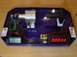
The actual Diode Torture Chamber is this. :yh:

attachment.php


I said i'd dress it up before this experiment really started, but then it dawned on me how much work i got myself into with this idea...

Even so it was many sleepless nights, to get it all done. I'll put it into a nice enclosure eventually, but doing it now would be torture for me, the idea here was to torture diodes...


Besides, it doesn't need to look pretty to kill diodes... :evil:


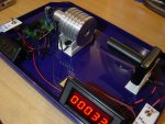
You can see all the main parts, and even how they are connected a little - i used a plastic base to mount and hold everything in place, but left it "naked" for the most part...

There are two power switches, the main power switch powers the counter (and the thermometer) separatelly first, so the counter remembers the number, even if i stop torture temporarily to re-plot a diode or check for degradation. The counter has 50h data memory, but i don't wanna have to rely on that unless there is a power outage (for which case there is also a secondary backup - a "time recorder", altho it's less accurate than the main setup - approx 2% instead of <1%).

The second switch starts or stops the cycler (so i can interrupt the experiment and do measurements)... The thermometer helps me make sure all measurements are done at the same temperature, or at least to see if a power difference is the result of temperature and not degradation...

There is also a pot, but it's hidden out of sight, since it's not something that would be adjusted all the time, it is currently set for exactly 1 minute ON, 1 minute OFF... Just left of the counter display you can also see it's own 5V power supply and the reset button, but that button does not get used much of course..

For now the counter and temperature displays are simply stuck to the edge of the base with double sided sticky foam.. Since the edge had an angle this resulted in the displays being in an easily viewable position.. Similar with the switches - i simply mounted them through L-shaped pieces of plastic stuck to the sides of the base, with double sided sticky-foam... The "sticky-foam" is heavy duty, meant for mounting mirrors on bathroom walls, so it's all a very strong construction, but at the same time it can easily be taken appart at any time (when i finally actually have some FREE TIME (one can dream) to put it in a nice enclosure)...

The wires are a little bit of a mess right now, but i'll tuck them away later...

I had to make holders for the heatsink and the sensor, in order to keep them aligned - i used L-shaped plastic and various 1mm thick bits of plastic sheets cut to the right shape - but most importantly i had to make the sensor itself! Of course the main part is the photo-transistor, but it can't be blasted by a laser directly, it would fry it at these power levels eventually (i know cos i fried one before), also it would be too sensitive to other light sources if exposed....

I had to find a way to eliminate all external influences, like shadows, artificial or natural light (before it would toggle the counter if i walked by and cast a shadow on it), so first i put it in a box, then i added that tube, which is also covered in black on the inside... Inside the tube slightly away from the photo transistor is a "calibrated diffuser" (don't ask what :angel:)... The tube is even cut at an angle, all to minimize light coming in from above, the reason i covered it in black on the inside is to prevent light from reflecting in through the tube...


The sensor turned out really great! Nothing but a laser will turn it on (tried all colors), and even a laser needs a certain minimum power (in case a diode dies but still lases a little like the FO3's). If a diode dies the sensor will not toggle the counter anymore, but this was easy to achieve, the tube and the diffuser inside the tube are what make the photo transistor immune to everything but lasers...


Here is another picture from a different angle.

attachment.php


This is all just temporary mounting for now, i used the simplest fastest approach i could take, to get it started sooner..

I just wrote around the switches with a felt tip pen, of course i'll clean it and replace it with printed labels now that it's running, just so it looks a little better.


I have to say, i'm VERY happy this is FINALLY done. From here on it can run completelly automated, and even if there was a power outage, when the power would come back on, it would continue, where it left off, i made double sure of that....


The time in the end will not be accurate down to seconds (if we get many hours as a result), there may be up to 1% of an error, but that doesn't really matter for our needs...


I think this is it, now i'm gonna go pass out for a couple of days...
Oh wait, i can't afford that, now that this is finally done, i get to go back to work... :undecided:
 

Attachments

  • P1 - Diode Torture Chamber v2 - FINISHED.JPG
    P1 - Diode Torture Chamber v2 - FINISHED.JPG
    546.5 KB · Views: 286
  • P2 - Diode Torture Chamber v2 - FINISHED.JPG
    P2 - Diode Torture Chamber v2 - FINISHED.JPG
    547.5 KB · Views: 283
Last edited:
awesome, looks great! :-)
..diodes will be all "wow, we are in some sort of amusement park" :-)

manuel
 
awesome, looks great! :-)
..diodes will be all "wow, we are in some sort of amusement park" :-)

manuel

Oh no, Manuel, you are wrong.

All the other diodes are shaking in their antistatic bags, when they hear the screams of the first one, since they don't know who's next...


Anyway, this is it. Now we just wait. :yh:

I'll write progress reports every so often, as i check the diode to see if it's showing any signs of degradation yet...
 
Now let's hope for 100 hours or more!

Indeed, and i don't care if my neighbours start complaining about the screams! :whistle:


Otherwise, i improoved the readibility of the plots posted a few posts back!

I used .PNG picture format, and while the quality is improoved to the same i see in Excel, the file size is actually smaller than .JPG in minimum compression setting.. I guess JPG is better for photos and such, which it's meant for.

But when it's important that colors don't mix, and lines stay sharp, PNG wins hands down!

I also reduced the scale of the X and Y axis since not all plots are extrapolated to 360mA yet...


I hope this helps. Definitelly not using JPG for plots anymore.
 
Are you able to take pics of the setup while the diode is on? or maybe some attempted murder video footage :)
 
Indeed, and i don't care if my neighbours start complaining about the screams! :whistle:


Otherwise, i improoved the readibility of the plots posted a few posts back!

I used .PNG picture format, and while the quality is improoved to the same i see in Excel, the file size is actually smaller than .JPG in minimum compression setting.. I guess JPG is better for photos and such, which it's meant for.

But when it's important that colors don't mix, and lines stay sharp, PNG wins hands down!

I also reduced the scale of the X and Y axis since not all plots are extrapolated to 360mA yet...


I hope this helps. Definitelly not using JPG for plots anymore.

Jpegs can be a pain to deal with especially on MSpaint. PNG images are the best for file size and quality. I noticed no degradation with my pics when compared to bitmaps

PNG is what I like to use on the PSP and the PDA I got
 
about efficiency and imperfections:
until now we were only speaking about imperfections on the facet, which increase and accumulate and all. shouldnt we be able to see either more scattered, diffuse light from the die, or dark areas on the facet, when there are such imperfections? speaking about differences in the 10% range, this wouldnt be much to detect, of course. but maybe it would yield some interesting results to look at a de-canned diode for scatter with a phototransistor or something, and have a look at the facet (off axis angle!) under a microscope with low optical output? a nightmare, thinking about the eye-risk!

if that all doesnt lead to anything, the impurities have to be in the cavity.. but then low-efficiency diodes shouldnt die earlier, when at the same thermal stress?

manuel

You reminded me of something very interesting with the above..


But first let me explain something.. These "imperfections" are NOT big enough to make themselves noticable in this manner. IF they were, the diode would not survive a single powerup.

The die has to be near perfect for the diode to even work.


The other thing is, that a LOT of this is just guessing. I don't really know where efficiency differences come from, i'm not a laser scientist, i am an amateur when it comes to this, and my assumptions are based on the experiences i gathered making over a hundred lasers and killing a bunch of diodes..

I know that high powers are easier to reach with higher efficiency diodes, and i know that some very low efficiency diodes can't even survive the currents where most others "thrive"...


BUT! This experience mostly comes from GGWs, and we already decided it's most likelly the early sleds contained prototypes, so it's VERY likelly that most of the low efficiency GGWs that gave me the bad experiences were prototype diodes never really meant to work in a 6x drive!


However you mentioned visible differences in output...

There are two things i would like to mention about this..

There is one thing i haven't mentioned yet.. While testing these 8x's, i noticed where the "splatter" comes from for the first time!

With every single diode i went looking for Ith..

Because of this i spent a lot of time at currents below lasing threshold, trying to find the spot where the first signs of lasing become apparent...

Well, i usually define Ith as the current where the power on my meter minus spontaneous emissions (i zero-in the LPM just under Ith, so spontaneous emissions are not included in the readings) measures 1mW...

The actual lasing threshold is actually a little lower, but for our purposes this is good enough IMO..


But the thing i wanted to mention was this. The "splatter" was evident long before any lasing occured! It had the exact same shape and form as the splatter we notice at higher powers, only that it was easier to see, not having been blinded by the spot!

So to me it looked like the splatter is the result of the ENTIRE DIE SURFACE producing some minimum light output in the form of spontaneous emissions.

I mean, the "splatter" as we call it is rectangular. And then, as i would raise the current, at the middle of one of the longer sides of this rectangle, the spot would appear and start becoming brighter and brighter - that spot is the point source of the stimulated emissions..


Because of this i got the feeling, that the entire surface is producing some light, and i also noticed that these spontaneous emissions forming the "splatter" become stronger with current, however not at the same rate as the spot becomes more powerful of course, so the spot drowns out a lot of the detail..

This is why i only really noticed it when i spent a lot of time under the lasing threshold, looking for Ith.


Another thing i'd like to mention is something else - what i called spontaneous emissions before this...


Last year, at some time i almost went blind on one eye, and had to stop using contacts for a while, and use glasses instead.

Unfortunatelly, my glasses block almost all 405nm light, and i really hate them for this..

But while playing with lasers, i noticed something interesting around the spot of PHRs with regular acrylic lenses.. I would suddenly see something i never noticed before.

There were usually two yellow-ish blobs around the slow axis of the spot if i recall correctly. One would be bigger, the other smaller.
The intensity of these two blobs would vary from diode to diode....


Later, when my eye healed, and i started using contacts again, i didn't see this, but as i was aware of it, i went looking for it, and for a while i was recording it with each diode i used - to see if it would matter with how long they survive...

That was when i started sorting diodes by wavelength, using relative comparisons through a special filter, and i would also make a note of this "yellow halo"...

With some diodes it was completelly absent, while others had it MUCH more noticable! So for a while i was making notes on the intensity of this yellow halo, to see if spontaneous emissions like that - guesstimated by several to be the result of impurities - would matter, when it comes to diode life...


Unfortunatelly (or luckily, since it was present almost everywhere?) i couldn't find any patternns or connections between "yellow-halo" intensity and diode failure rate...

But this was in the time before i knew of the "splatter", since i didn't have good working glass lenses yet.


With these 8x's it was the first time i was testing a LARGE batch of diodes using the 405-G-1 lens....

And at around diode five or six it occured to me to test wavelength as well.. Suddenly i would notice the yellow halo again. Since i tried comparing the wavelengths to my wavelength reference lasers, and those use AixiZ lenses, the yelow halo of 8x's seemed HUGE in comparison! But it was only because of the short FL of the lens used in them...


This was also the first time i noticed the "yellow halo" AND the "splatter" at the same time.

The yellow halo is only visible after the filter, since the 405nm (and blue-ish colors) are blocked with a yellow filter.

But having spent quite some time below Ith i was able to observe both at once projected on a sheet of paper....


Since there are a few diodes where i didn't test the wavelength yet, i should repeat these tests, and try to capture a good splatter picture without the interference of the spot, as well as the halo i am talking about.


As i already said, i don't know if it even means anything or not, but it did show big variations between individual diodes, just like with GGWs.. But at the same time it is not related to their wavelengths or anything else as far as i can tell...
 
Are you able to take pics of the setup while the diode is on? or maybe some attempted murder video footage :)


Of course. :yh:

I will take some pics of the setup, with the laser beam visible. Before i just wanted to quickly show what the finished setup looks like, since i was quite excited about it's completion.


As for the video. This is something i was wondering about myself - would anyone request a video? :D


It would be quite a boring video. Three minutes would show the laser ON twice and OFF once, or vice versa... :crackup:


But if you guys want, i can make a video, just so you see how the beam comes ON and the number on the counter goes up by 1... :yh:

Oh and the relay makes a little click sound.. Does the video have to have sound? :whistle:


But in any case, first i need to get some sleep....

Maybe a video in 5x the speed. Nah no sound needed, unless there's something to hear, like maybe screams. BTW, did you say before that multiple diodes could be tortured at the same time with your setup?
 
Maybe a video in 5x the speed. Nah no sound needed, unless there's something to hear, like maybe screams. BTW, did you say before that multiple diodes could be tortured at the same time with your setup?

I think it can only do one at a time. That doesn't really matter though. We have to kill one BEFORE we decide what to do with the second.

Peace,
dave


Back
Top