IgorT
0
- Joined
- Oct 24, 2007
- Messages
- 4,177
- Points
- 0
Did you not read my original reply to you?!? I spent like half an hour writing that!
Maybe i try too hard, and then people shun away from reading? :undecided:
Check out this for now:
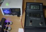
This is my Laser Power Meter, connected to my Diode Analyzer v1, at the end of plotting the 8x laser i made for FrancoRob....
In the meanwhile the Diode Analyzer also has a temperature display in v2.
I use it to create P/I/V plots of diodes all the time - it was made to make plotting easier, safer and faster all at the same time!
It has two pots for "hand-plotting", one sets the max current, the other then adjusts from 0-100% of this current... The two displays show If (forward current and Vf (diode forward voltage at that current).
The Imax pot is basically a sort of safety, because the Iadj pot can't possibly go higher than the max set by the Imax pot.
This allows me to safelly turn the pot with the diode attached!
In the new version a third display also shows the temperature now..
The two switches - the first switches between an internal "dummy load" and the diode, the other switches between 0.7A and 2A ranges of max current...
Anyway that's the Diode Analyzer (aka OmniDrive)...
The new Cycler Circuit was made to torure diodes by simulating "average" laser use, turning the laser ON for a minute and OFF for a minute (adjustable by a pot)..
At the same time a photo-transistor is blasted aagainst by the laser, and triggers a counter. The counter then in effect counts the minutes (or whatever the cycler is set to) and displays them on a big LED display.
When the diode dies, the power drops to a a few mW or less, so the beam does not trigger the photo-transistor anymore, the counter stops counting (or a digital timer stops timing)
All this is completelly battery powered for total ESD protection!
Eventually all three will also be connected to a computer for total interconnectivity, and control from a program i will write for this purpose.
At the moment only the LPM connects to the computer (for power stability graphs) while the Diode Analyzer can connect to the meter, so the meter also sends current data to the computer..
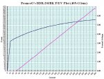
This is how i make those PIV graphs....
The plots on the other hand tell us what power comes out of the diode at what current (the violet line), and what the diode forward voltage at that current is (the blue line)...
I'll have to dress up the Cycler in a nice box and take some photos, cos it's still in it's raw state right now (nekkid).
That's my analyzing equipment.


