

Garoq
0
- Joined
- Aug 27, 2010
- Messages
- 1,525
- Points
- 83
As promised, this is a tutorial on how to use the new Survival Laser S4X host in a build with the NUBM44 diode and Lazeerer's SXD rectangular driver set at 4.5A. This driver requires heatsinking and will be used with our new driver heat sink pill in this build.
First, gather the necessary components (L-R): SL S4X host assembly, Flaminpyro's 9mm diode press, DTR's 9mm copper diode module, DTR's NUBM44 diode (or optionally DTR's NUBM44 diode already pressed in a copper module), SL 16.8mm blank battery contact board, SL 16.8mm brass ring, SL driver heat sink pill, SL extended and tapered copper heat sink with set screw and Allen wrench, a couple pieces of heat shrink tubing about 5/16" long, Lazeerer's SXD 4.5A laser driver with lead wires attached.
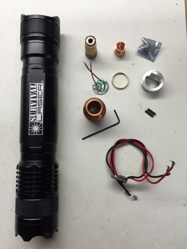
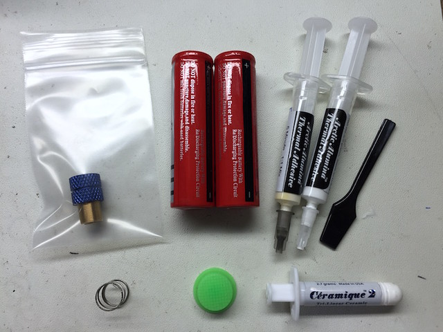
(Components list continued) SL G-2 lens assembly with blue anodized extended focus ring, your choice of two 18650 Li-ion batteries, Arctic alumina thermal adhesive, SL external lens spring, lens cap, Ceramique thermal compound. Not shown: solder, flux, etc.
Using the Flaminpyro 9mm diode press, install the NUBM44 diode into the 9mm copper diode module.
Cut the battery side leads of the driver to about 1/2" long, strip and tin about 3/32".
Remove the stock wires (if any) from the blank battery contact board and solder the battery side driver wires to the appropriate spots on the board. Note: I would advise checking your work on the driver periodically with a dummy load and regulated power supply to make sure you haven't shorted something during assembly, before the driver and pill assembly is completed.
Thread the driver and wires through the larger I.D. of the brass ring and solder the blank battery contact board to the ring in two spots.
Wipe the driver "shelf" of the pill with alcohol or acetone to remove any oil or grease and let dry. This will promote better bonding of the thermal adhesive to the pill.
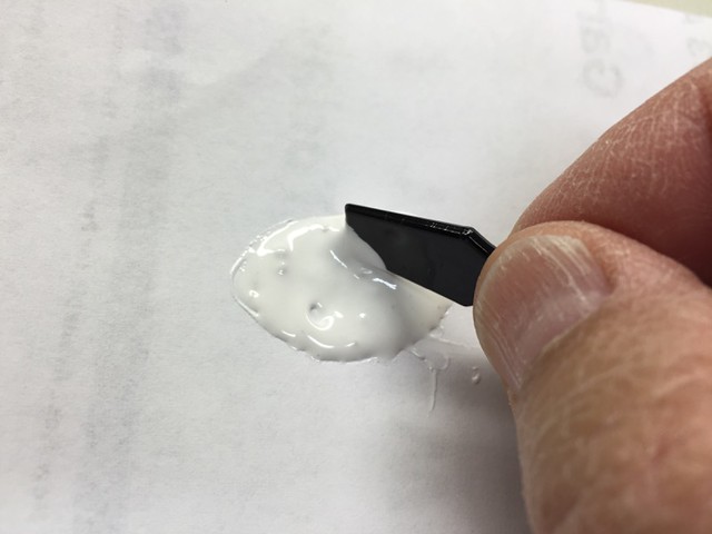
Mix a small amount of the Arctic Alumina thermal adhesive and apply a thin layer to the controller chip and adjoining capacitor, and the pill shelf as shown. Allow to cure thoroughly before proceeding. Note: The capacitor at the battery end of the driver board could potentially be shorted if it touches the pill. The thin layer of thermal adhesive will prevent any shorting. It will also help to create a stronger bond between the driver and the pill.
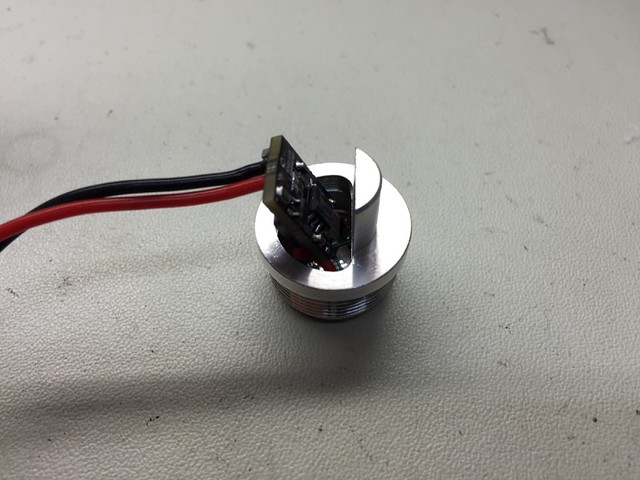
After the thermal adhesive has cured, thread the driver assembly through the large opening in the driver heat sink pill as shown.
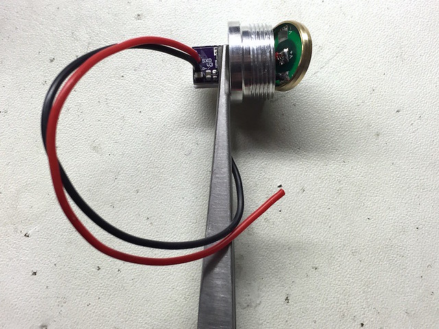
Mix about 1 gram of the thermal adhesive and apply a small amount to the controller side (the side with the smaller components and opposite from the adjustable pot) of the driver board. Press the driver board against the driver shelf of the pill with the top (diode) end of the board flush with the top of the shelf. Carefully align the board in proper position on the shelf and hold there with finger pressure until the adhesive has set (about 3-5 minutes).
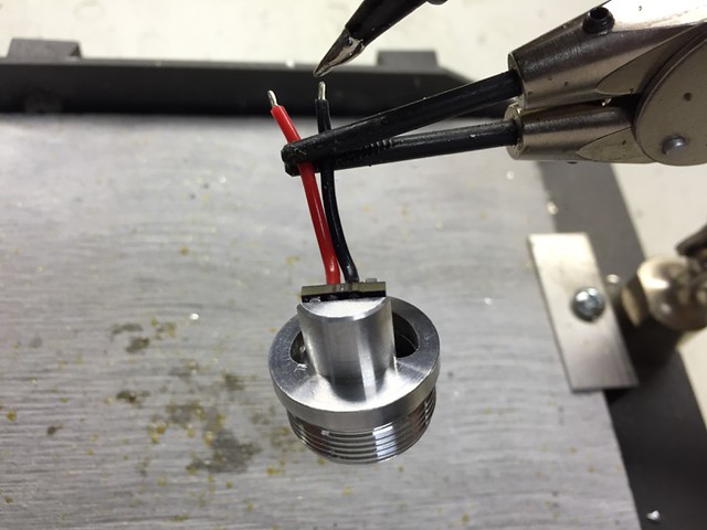
A customer recommended the use of clamping tweezers to hold the driver in position on the shelf while the epoxy cures, which works really well!
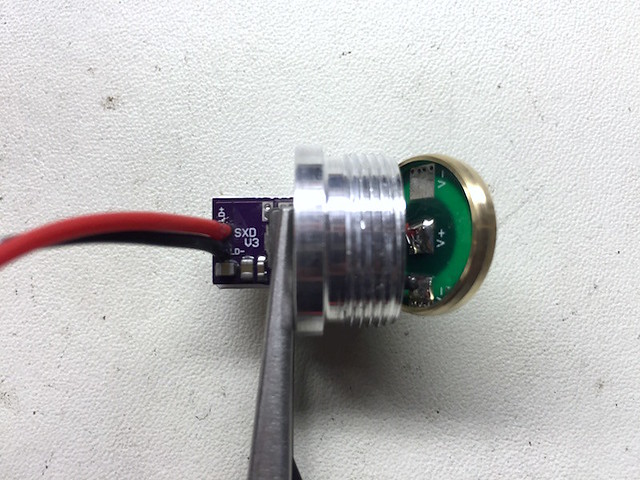
Note the relative position of the diode module, heat sink and driver and pill assembly. Trim the diode side wires of the driver to about 1" long. You want the wires long enough so that the diode module will stick out sufficiently to apply the thermal compound to the diode module during final assembly, but short enough that you will still be able to compress the excess wire within the heat sink.
Strip and tin approximately 3/32" of the diode side wires of the driver.
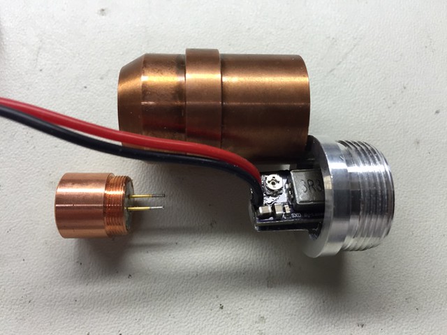
Side view of the diode and driver assembly prior to pressing in the brass ring. I used this particular sequence of assembly to make it easier to align and bond the driver to the pill heat sink shelf. Slip the heat shrink tubes over the diode side driver wires.
CAUTION: Allow the thermal epoxy to cure for several hours (preferably overnight) before proceeding to the next step. If the epoxy is still soft, the driver could move or pop off the driver shelf of the pill when you press in the battery contact board & brass ring assembly.
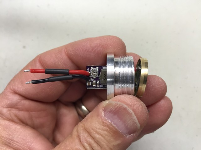
Using pliers or a drill press with a small arbor, gently press the brass ring into the recess of the pill, working around the perimeter of the pill until the brass ring is flush with the pill.
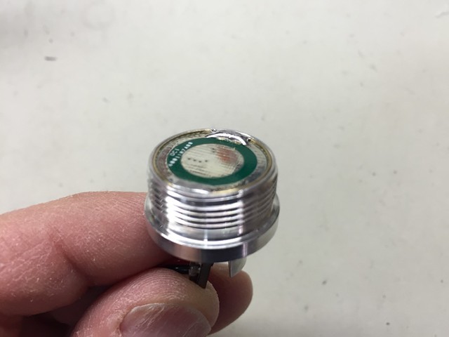
Make one last check of the proper operation of your driver and pill assembly with your dummy load and power supply. After testing, disconnect the assembly from your test setup and touch the two output wires together to dissipate any remaining charge from the driver circuit.
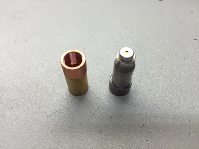
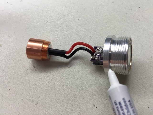
NOTE: DTR recently recommended using his half-height copper diode module back half on this build for better heat transfer.
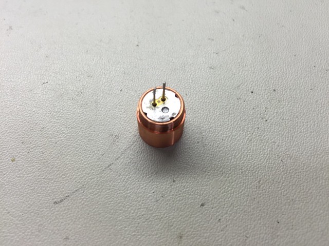
Here are some photos of the new short back half being used in an SL-5 diode and driver module:
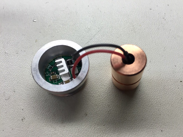
The wires were a fairly tight fit, probably because the diode pins are off center and the heat shrink tubing takes up extra space. If you use these you may want to consider opening up the hole a little bit to make everything fit better.
Also, Ricker recently posted an excellent build thread of his laser using mostly the same components, where he also used the short diode module back half. He included some excellent pictures documenting the process:
http://laserpointerforums.com/f65/my-first-build-pic-heavy-s4x-w-nubm44-96423.html
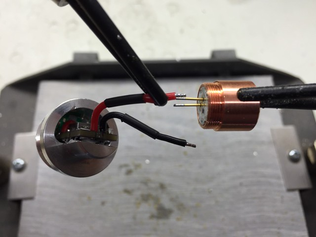
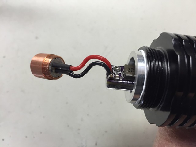
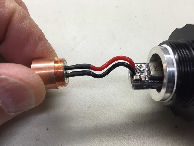
Align and solder the driver wires to the diode leads, observing proper polarity of the diode.
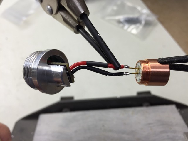
Slip the heat shrink tubes over the diode solder joints.
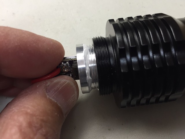
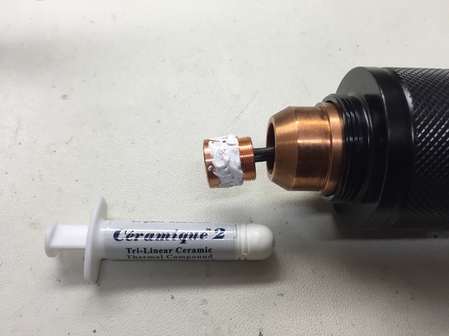
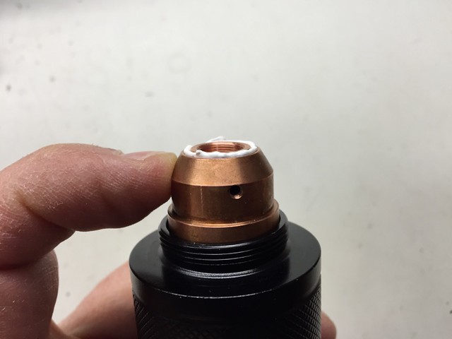
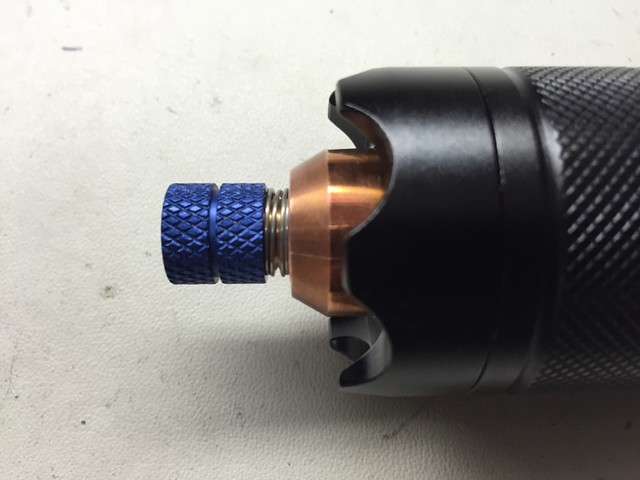
Apply a small bead of Ceramique thermal compound under and around the flange on the driver heat sink pill.
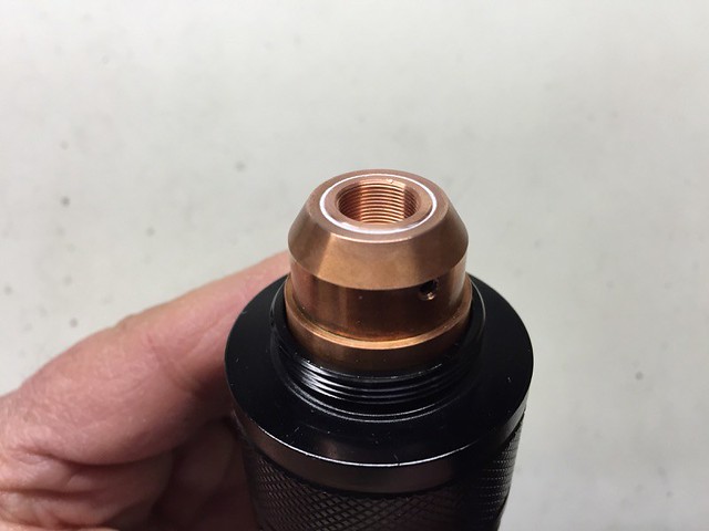
Thread the diode and driver module into the finned end of the battery holder portion of the host until it is fully seated.
Wipe off any large excess of thermal compound. A small amount left is OK.
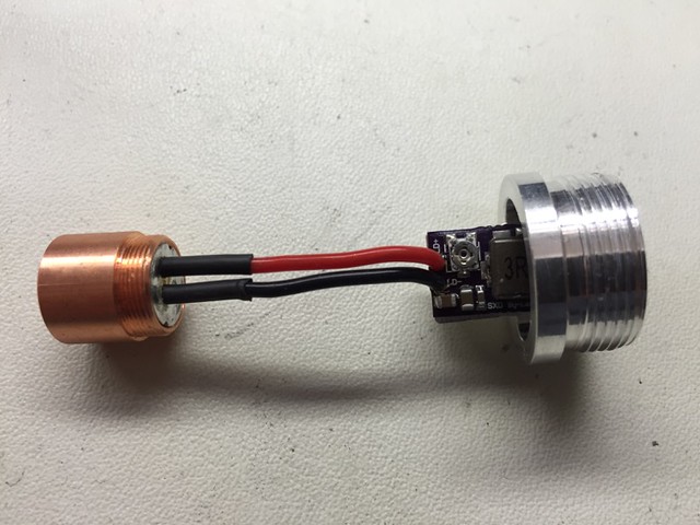
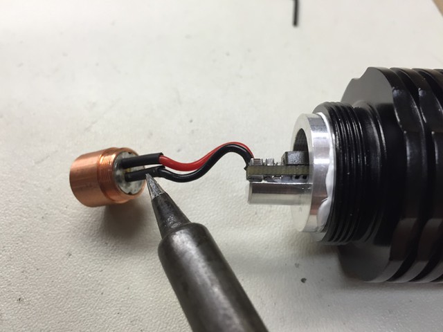
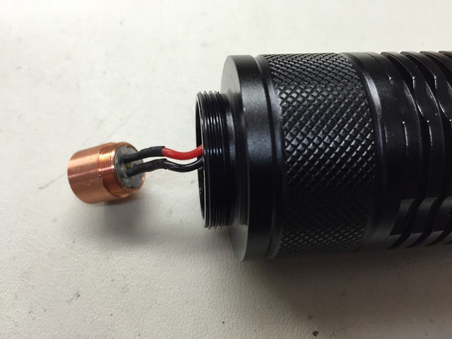
Using the tip of the soldering iron, lightly brush the surface of the heat shrink tubes until they shrink tightly on the diode solder joints (remove excess solder from the tip before doing this).
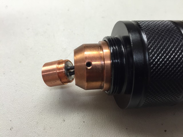
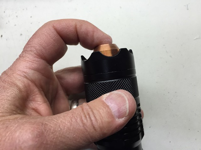
Slip the heat sink holder portion of the host over the diode module and exposed diode and driver assembly, and thread onto the battery holder portion of the host until seated.
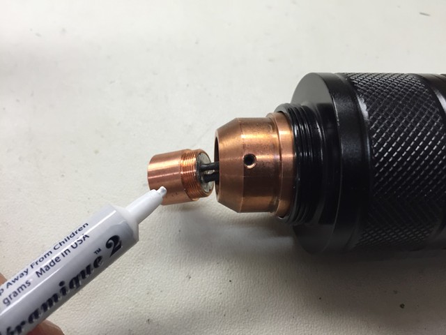
Slip the extended and tapered copper heat sink over the diode module and seat within the heat sink holder so that the diode module projects slightly beyond the heat sink. Note: The lens assembly may be used as a tool to secure the diode module and pull it through the heat sink.
Apply a very small amount of Ceramique thermal compound to the outside surface of the diode module.
Using your finger, gently press the diode module into the heat sink until the end of the module is flush with the end of the heat sink, and securely tighten the set screw in the heat sink against the module. Caution: do not get any Ceramique thermal compound inside the diode module during this process. Again, the lens assembly may be used as a tool to precisely position the module in the heat sink.
Wipe off any excess thermal compound from the diode module/heat sink junction.
Thread the bezel onto the heat sink holder portion of the host, and holding the heat sink with your finger to prevent it from rotating, tighten the bezel securely onto the heat sink holder.
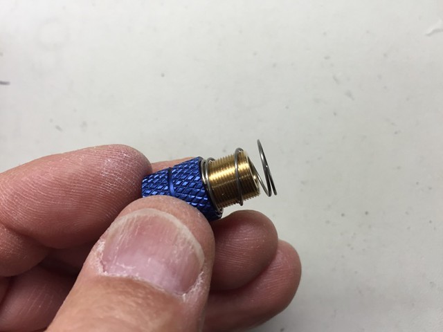
Place the external lens spring over the exposed lens barrel of the G-2 lens assembly.
Thread the G-2 lens and lens spring assembly into the diode module, leaving about a 3/32" gap between the focusing ring and the heat sink. Perform final focusing after the laser is "live".
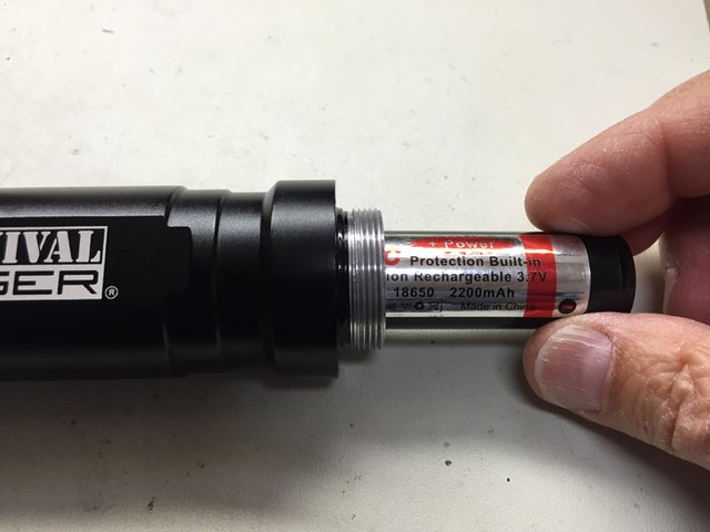
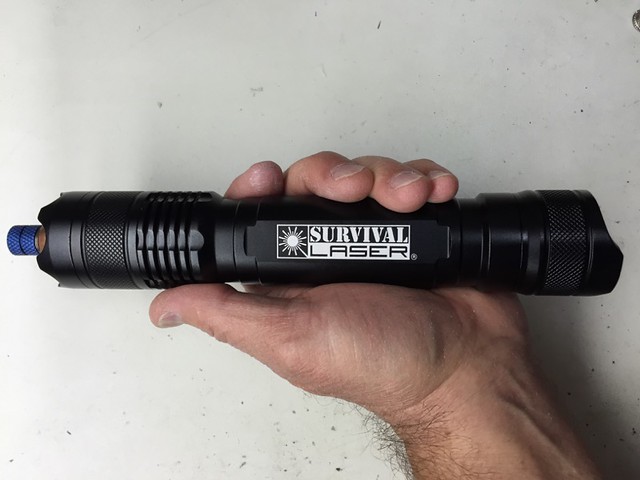
Now is the time for you to put on your appropriate laser safety goggles. Install two (2) 18650 Li-ion batteries in the battery holder, positive end first. Point your laser in a safe direction and thread the tailcap and switch assembly onto the laser until seated. If the laser starts operating, click the tailcap switch off. The laser is now ready for use.
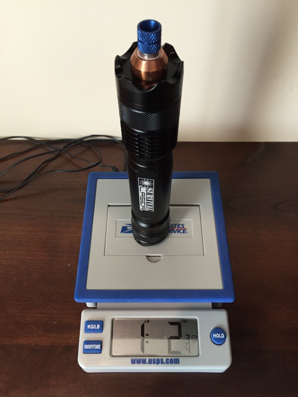
I immediately aimed the laser on my "5 watt" Ophir head LPM and the readout displayed a peak output in the 7.2 - 7.3 watt range. Clearly I need a more capable LPM now.") As far as duty cycles go, based on my initial observations this laser should be good for at least a couple minutes of "on" time. I'll update with more information and photos as my testing continues. Thanks for viewing! :beer:
As far as duty cycles go, based on my initial observations this laser should be good for at least a couple minutes of "on" time. I'll update with more information and photos as my testing continues. Thanks for viewing! :beer:
First, gather the necessary components (L-R): SL S4X host assembly, Flaminpyro's 9mm diode press, DTR's 9mm copper diode module, DTR's NUBM44 diode (or optionally DTR's NUBM44 diode already pressed in a copper module), SL 16.8mm blank battery contact board, SL 16.8mm brass ring, SL driver heat sink pill, SL extended and tapered copper heat sink with set screw and Allen wrench, a couple pieces of heat shrink tubing about 5/16" long, Lazeerer's SXD 4.5A laser driver with lead wires attached.
(Components list continued) SL G-2 lens assembly with blue anodized extended focus ring, your choice of two 18650 Li-ion batteries, Arctic alumina thermal adhesive, SL external lens spring, lens cap, Ceramique thermal compound. Not shown: solder, flux, etc.
Using the Flaminpyro 9mm diode press, install the NUBM44 diode into the 9mm copper diode module.
Cut the battery side leads of the driver to about 1/2" long, strip and tin about 3/32".
Remove the stock wires (if any) from the blank battery contact board and solder the battery side driver wires to the appropriate spots on the board. Note: I would advise checking your work on the driver periodically with a dummy load and regulated power supply to make sure you haven't shorted something during assembly, before the driver and pill assembly is completed.
Thread the driver and wires through the larger I.D. of the brass ring and solder the blank battery contact board to the ring in two spots.
Wipe the driver "shelf" of the pill with alcohol or acetone to remove any oil or grease and let dry. This will promote better bonding of the thermal adhesive to the pill.
Mix a small amount of the Arctic Alumina thermal adhesive and apply a thin layer to the controller chip and adjoining capacitor, and the pill shelf as shown. Allow to cure thoroughly before proceeding. Note: The capacitor at the battery end of the driver board could potentially be shorted if it touches the pill. The thin layer of thermal adhesive will prevent any shorting. It will also help to create a stronger bond between the driver and the pill.
After the thermal adhesive has cured, thread the driver assembly through the large opening in the driver heat sink pill as shown.
Mix about 1 gram of the thermal adhesive and apply a small amount to the controller side (the side with the smaller components and opposite from the adjustable pot) of the driver board. Press the driver board against the driver shelf of the pill with the top (diode) end of the board flush with the top of the shelf. Carefully align the board in proper position on the shelf and hold there with finger pressure until the adhesive has set (about 3-5 minutes).
A customer recommended the use of clamping tweezers to hold the driver in position on the shelf while the epoxy cures, which works really well!
Note the relative position of the diode module, heat sink and driver and pill assembly. Trim the diode side wires of the driver to about 1" long. You want the wires long enough so that the diode module will stick out sufficiently to apply the thermal compound to the diode module during final assembly, but short enough that you will still be able to compress the excess wire within the heat sink.
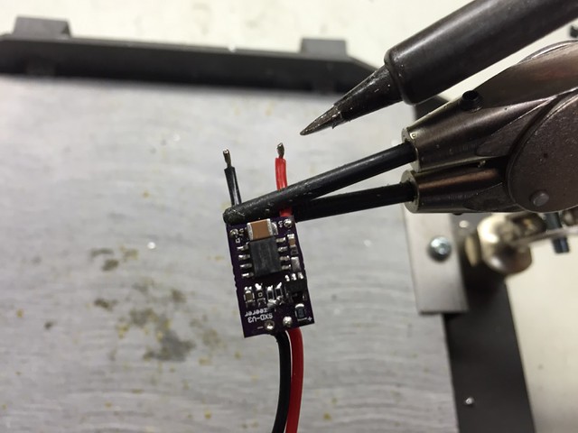
Strip and tin approximately 3/32" of the diode side wires of the driver.
Side view of the diode and driver assembly prior to pressing in the brass ring. I used this particular sequence of assembly to make it easier to align and bond the driver to the pill heat sink shelf. Slip the heat shrink tubes over the diode side driver wires.
CAUTION: Allow the thermal epoxy to cure for several hours (preferably overnight) before proceeding to the next step. If the epoxy is still soft, the driver could move or pop off the driver shelf of the pill when you press in the battery contact board & brass ring assembly.
Using pliers or a drill press with a small arbor, gently press the brass ring into the recess of the pill, working around the perimeter of the pill until the brass ring is flush with the pill.
Make one last check of the proper operation of your driver and pill assembly with your dummy load and power supply. After testing, disconnect the assembly from your test setup and touch the two output wires together to dissipate any remaining charge from the driver circuit.
NOTE: DTR recently recommended using his half-height copper diode module back half on this build for better heat transfer.
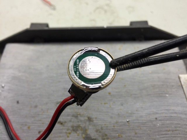
Here are some photos of the new short back half being used in an SL-5 diode and driver module:
The wires were a fairly tight fit, probably because the diode pins are off center and the heat shrink tubing takes up extra space. If you use these you may want to consider opening up the hole a little bit to make everything fit better.
Also, Ricker recently posted an excellent build thread of his laser using mostly the same components, where he also used the short diode module back half. He included some excellent pictures documenting the process:
http://laserpointerforums.com/f65/my-first-build-pic-heavy-s4x-w-nubm44-96423.html
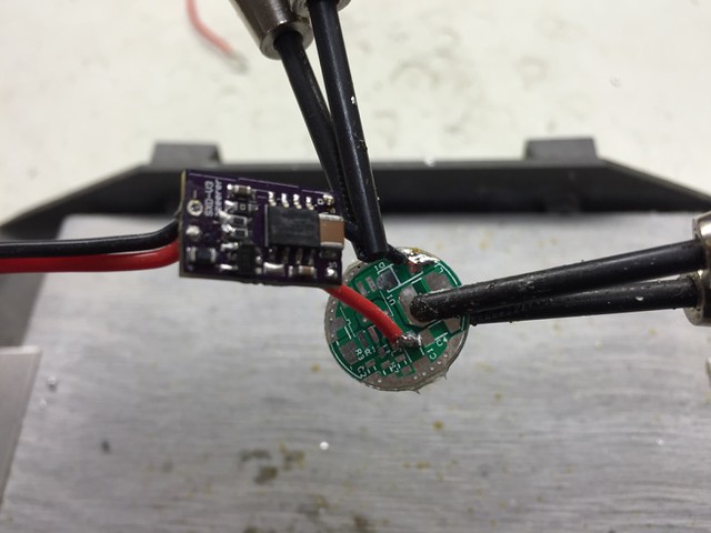
Align and solder the driver wires to the diode leads, observing proper polarity of the diode.
Slip the heat shrink tubes over the diode solder joints.
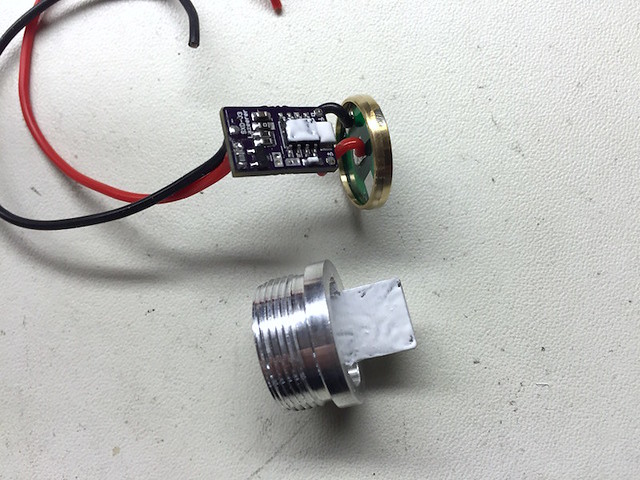
Apply a small bead of Ceramique thermal compound under and around the flange on the driver heat sink pill.
Thread the diode and driver module into the finned end of the battery holder portion of the host until it is fully seated.
Wipe off any large excess of thermal compound. A small amount left is OK.
Using the tip of the soldering iron, lightly brush the surface of the heat shrink tubes until they shrink tightly on the diode solder joints (remove excess solder from the tip before doing this).
Slip the heat sink holder portion of the host over the diode module and exposed diode and driver assembly, and thread onto the battery holder portion of the host until seated.
Slip the extended and tapered copper heat sink over the diode module and seat within the heat sink holder so that the diode module projects slightly beyond the heat sink. Note: The lens assembly may be used as a tool to secure the diode module and pull it through the heat sink.
Apply a very small amount of Ceramique thermal compound to the outside surface of the diode module.
Using your finger, gently press the diode module into the heat sink until the end of the module is flush with the end of the heat sink, and securely tighten the set screw in the heat sink against the module. Caution: do not get any Ceramique thermal compound inside the diode module during this process. Again, the lens assembly may be used as a tool to precisely position the module in the heat sink.
Wipe off any excess thermal compound from the diode module/heat sink junction.
Thread the bezel onto the heat sink holder portion of the host, and holding the heat sink with your finger to prevent it from rotating, tighten the bezel securely onto the heat sink holder.
Place the external lens spring over the exposed lens barrel of the G-2 lens assembly.
Thread the G-2 lens and lens spring assembly into the diode module, leaving about a 3/32" gap between the focusing ring and the heat sink. Perform final focusing after the laser is "live".
Now is the time for you to put on your appropriate laser safety goggles. Install two (2) 18650 Li-ion batteries in the battery holder, positive end first. Point your laser in a safe direction and thread the tailcap and switch assembly onto the laser until seated. If the laser starts operating, click the tailcap switch off. The laser is now ready for use.
I immediately aimed the laser on my "5 watt" Ophir head LPM and the readout displayed a peak output in the 7.2 - 7.3 watt range. Clearly I need a more capable LPM now.
As far as duty cycles go, based on my initial observations this laser should be good for at least a couple minutes of "on" time. I'll update with more information and photos as my testing continues. Thanks for viewing! :beer:
Last edited:


")