Welcome to Laser Pointer Forums - discuss green laser pointers, blue laser pointers, and all types of lasers

Buy Site Supporter Role (remove some ads) | LPF Donations

Links below open in new window

FrozenGate by Avery

4 diodes better than 1. DIY Array on the cheap

Hemlock Mike said:
Ref ---

You may be right in that --- I only remember their attempts at Greek Fire!

Mike
They did the greek fire after they couldn't get the mirror to set it on fire if I remember correctly.
Either way there is no proof that it never worked nor is there proof that it did. So its just a myth, legend, story.

------------------
Keep up the good work, I wanna see how this turns out.


Your reffering to archamede's death ray. They did two eppisodes on this, the second one was a little more elaborate, and had more sucess, but cant remember if they called that one busted.


Hemlock Mike said:
Wannaburn ---

 Many people have tried this - I saw some experimenting over on PL too.  I played with it and had limited success.
I also think Andy.con gave up on his attempts but it is sure fun to try.

Mike

There is a gent on PL that put the flame under my butt on this one. His build made me drool! Just incredible workmanship on a 24 diode array but red.

I saw andy_cons thread, he didnt seem to have the drive to complete it, but made a valiant effort none the less.


Spyderz20x6 said:
Nice freakin' pics :o
Set each diode to 120mA... Then you will have some real power!

How are you powering it? Batteries or PSU?


I have it low until all is figured out, I ran it at 300mW just to watch the temp, and see what im dealing with. I have also the desire to avoid aditional extended exposure, and always turn them up last, after completion. The 803's all have their individual needs, and right now its a single driver pushing them in paralell. Running them too high might land me LED's , which will be a pain if I have to replace and re-align. Gives a whole new meaning to RE & RE ;)


*Its powered with a 10v lead from a PC pwer supply. But with the driver im using can run it just as well from an unregulated 12v wall adaptor.
 
An interesting finding is what happens to the beams when passed through the lenses as pictured.
You cant really see it as clear on the cam, but the individual beam thins right down like a well built green.

This is going to make an interesting point to the sharpness and clarity of the final beam, or so it would seem. I had them down to the size of my older 400$ 7mW leadlight and the divergence of the single beams were small and at a good distance. Though there is losses with the lenses, there may also be an equal balance of good that comes with them.


I also found this photo on PL, same concept as the others seen, but the only BR looking so far.
 

Attachments

  • front3.jpg
    front3.jpg
    123.1 KB · Views: 510
Somehow that rendering makes all of it look huge, like som stadium-sized doomsday device :)
 
Fantastic pictures :) Very nice setup as well, it looks like you have used the turning blocks from PS3 sleds for your 1st 90 degree turn, I have used them and found that they are prefect for the job as they were designed for Blu ray LD's, so as you say....
The optics arent causing much of a loss

I look forward to further developments.

Regards rog8811
 
rog8811 said:
Fantastic pictures :) Very nice setup as well, it looks like you have used the turning blocks from PS3 sleds for your 1st 90 degree turn, I have used them and found that they are prefect for the job as they were designed for Blu ray LD's, so as you say....
The optics arent causing much of a loss

I look forward to further developments.

Regards rog8811

Thanks, im having fun playing with different ideas and taking pictures of course;) Lasers seem to be very photogenic, no matter what the setup.

You are correct, the 'mirriors' are the same you speak of. I have some first surface glass, but dont want to scratch them while figurung things out. The other ones, lets just say is from an unlimited supply ::)

They also make great combiners for green and red or green and violet. They are small, but so are the beams ;)


---------------------------------------------------------------------------------------------------------------------------------------------


Anyone know if 4 LM317's can be mounted to a single H/S, without isolating them from one another?

I havent tried this yet, but am thinking it will adjust them as one?  Or would it just be a better idea to keep them on seperate heatsinks?

Im working on the driver, and dont want to etch the board until the details are hammerd out.


----------------------------------------------------------------------------------------------------------------------------------------


andy_con said:
i stopped building for the reason i Pm'ed you about

Just out of curiosity, what patent exactly were you reffering to in the PM?  I want to be sure and avoid stepping on toes. I have seen many versions of this type af build, including a member of PL's, rendition in a previous post. Not too mention the exact duplicates made by students. Im a bit confused by this.. :-/
 
Yeah... you can theoretically parallel multiple LM317 to increase the output
current capacity to a single load.. 8-) I've done it  a while back to supply about
2 Amps to a circuit when I only had LM317 on hand. There are higher power LM317
regulators available... I can't remember off hand (IIRC LM350)..


Or are you talking about 4 separate LM317 Circuits.... :-? :-? :-?

[EDIT]
If so... The Mounting tab is Ground and if all the grounds are from the same
supply... there should be no problems.. ;)
 
lasersbee said:
Yeah... you can theoretically parallel multiple LM317 to increase the output
current capacity.. 8-) I've done it  a while back to supply about 2 Amps to
a circuit when I only had LM317 on hand. There are higher power LM317
regulators available... I can't remember off hand (IIRC LM350)..


I have the LM350's but reserve them for diodes of higher power, besides they are much more expensive. I only need 4-450ma on this build, as the power in mW will be decent, and so will the life of the diodes (I hope) But if the 317's link together via the H/S tab, can I still adjust 4 of them individually? Or will one resistor / trimpot change the leavel on all four?
 
wannaburn said:
[quote author=lasersbee link=1229985350/20#23 date=1230081214]Yeah... you can theoretically parallel multiple LM317 to increase the output
current capacity.. 8-) I've done it  a while back to supply about 2 Amps to
a circuit when I only had LM317 on hand. There are higher power LM317
regulators available... I can't remember off hand (IIRC LM350)..


I have the LM350's but reserve them for diodes of higher power, besides they are much more expensive. I only need 4-450ma on this build, as the power in mW will be decent, and so will the life of the diodes (I hope) But if the 317's link together via the H/S tab, can I still adjust 4 of them individually? Or will one resistor / trimpot change the leavel on all four?


[/quote]
For what you are doing... Knowing that all Blu-Ray diodes do not have identical characteristics...
you best bet is to use one (1) driver per Laser Diode... then you can adjust each one individually.
Makes tweaking a lot simpler...  ;)
Or are you trying to win a prize for the least amout of parts used.... ;D ;D ;D ;D ;D  
 
Hey wannaburn...
I just saw a patent from 2005 of a similar setup on another
forum.

http://www.photonlexicon.com/forums/attachment.php?attachmentid=3469&d=12186 18183

The guy is using 2 sets of 8 beams as far as I can figure... too bad its in
German... might as well be in Chinese...

If any one can read it... would be nice to know what the patent actually entails.
Is it the combining of beams... the mirror mounting method... The types of laser
diodes... or just a way of combining multiple laser diodes.. :-?

I'd be watching out for the Patent Cops.... ;D ;D ;D ;D

Jerry
 
Ill keep one eye open while I sleep ;)


The question for the driver, is not how to use one lm317, but four of them. The problem at hand is, if I mount all 4, 317's on the same heatsink without isolating them. They (all 4) would be sharing a common center pin. Seeing as the center pin is used to adjust the current, would this make all 4 adjust from one trimpot? or could they still be adjusted individually by their own pots? still sharing that center pin via the H/S
 
wannaburn said:
Ill keep one eye open while I sleep ;)


The question for the driver, is not how to use one lm317, but four of them. The problem at hand is, if I mount all 4, 317's on the same heatsink without isolating them. They (all 4) would be sharing a common center pin. Seeing as the center pin is used to adjust the current, would this make all 4 adjust from one trimpot? or could they still be adjusted individually by their own pots? still sharing that center pin via the H/S

Sorry wannaburn... Your correct... I was thinking of a 7805 regulator... You will need to isolate the the
mounting tabs... if not you will only be able to use 1 trimpot and associated circuitry to output 1
common current... and depending on each diode's characteristic they will not necessarily output the
same power... That common setup feels risky... I would build 4 separate LM317 circuits anbd isolate
the tabs on a common HS.

Just mt $0.02
 
You probably will see some mixing of the feedback current with all the tabs common. I'd use mylar insulator pads and heatsink grease. Common ground will be through the LD's. The tab is the refference in each circuit. (I think)

Mike
 
lasersbee said:
[quote author=wannaburn link=1229985350/20#27 date=1230083483]Ill keep one eye open while I sleep ;)


The question for the driver, is not how to use one lm317, but four of them. The problem at hand is, if I mount all 4, 317's on the same heatsink without isolating them. They (all 4) would be sharing a common center pin. Seeing as the center pin is used to adjust the current, would this make all 4 adjust from one trimpot? or could they still be adjusted individually by their own pots? still sharing that center pin via the H/S

Sorry wannaburn... Your correct... I was thinking of a 7805 regulator...  You will need to isolate the the
mounting tabs... if not you will only be able to use 1 trimpot and associated circuitry to output 1
common current... and depending on each diode's characteristic they will not necessarily output the
same power... That common setup feels risky... I would build 4 separate LM317 circuits anbd isolate
the tabs on a common HS.

Just mt $0.02[/quote]


Hemlock Mike said:
You probably will see some mixing of the feedback current with all the tabs common.  I'd use mylar insulator pads and heatsink grease.   Common ground will be through the LD's.   The tab is the refference in each circuit.   (I think)  

Mike


Thanks guys, just got in from xmas last minute shopping. Its 2:15am, luckily Wallymarts 24hrs during the season for a week or two :)

Im thinking of just using the four 317's but il just go with seperate, and smaller H/S's. It not like they are open can reds, so I dont see heat being a problem. Maybe a small fan for added cooling. The next couple of days are going to be a write off, bah-humbug!
But will slip in as much work as possible and aim for some progress, and of course add some pics.
 
Hemlock Mike said:
You probably will see some mixing of the feedback current with all the tabs common.  I'd use mylar insulator pads and heatsink grease.   Common ground will be through the LD's.   The tab is the refference in each circuit.   (I think)  

Mike
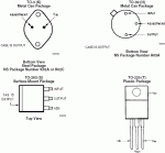
The center tab is Vout:
 

Attachments

  • LMx17_pins.gif
    LMx17_pins.gif
    15.5 KB · Views: 363


Back
Top