randomlugia said:
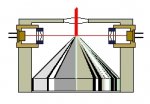
Hmmm... Couldn't you use use a second lens to keep them in one beam? Example:
Unfortunately, its easier said than done. When 4 seperate beams enter the optics, you will always get 4 out. I believe the idea is to live with this problem, but get the beams closer together in paralell. So essentially you still have 4 beams in the final output, but they are so close together, they behave as one.
The cube used in the setup (pending) somehow eliminates the difficulty in bringing them together, but id imagine they still remain as 4 seperate beams tightly paralelled.
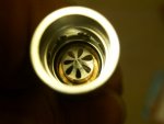
To see this behavior up close, take two diodes with raw output, and no focusing lens on the end of the modules. Place them close together and power them up. Now put a larger collimating lens infront of the both of them. Voila! lol, two seperate beams

They will always remain as seperate beams, travelling on their own paths. Ive tried many optics in the past to try and achieve this. Ive tried the above with two modules side by side, focused them down together, placed an expander in the path and them collimate again after the expander. Guess what, two beams again
If there is one thing ive learned in my time trying different things, is that to get more power, mainly by combining, things become very tricky. Combining of different wavelengths is much easier than this, and is a good start to begin understanding.
@ suiraM-
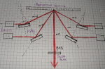
That is an interesting idea, though it sounds equally as involved as the route ive chosen. Do you by any chance have a crude sketch or diagram to aid and illustrate the proceedure? I'd like to give this one a try as well, but would expect the losses to be a bit more than my current arrangement.
I had thought of trying a diffraction gratting, but hadnt put much time in the idea. The problem with BR that I also see for this, would be the absorbtion of the gratting material itself, but may be wrong.
I cant picture this arangement in my head, but if you can post a pic, im sure things will become much clearer.
As usual, all input is welcome ;D
And Merry Christmas to all
")


")