Welcome to Laser Pointer Forums - discuss green laser pointers, blue laser pointers, and all types of lasers

LPF Donation via Stripe | LPF Donation - Other Methods

Links below open in new window

ArcticMyst Security by Avery

Learn From Mistakes That Can Happen To Anybody...

Joined
Feb 5, 2008
Messages
6,252
Points
83
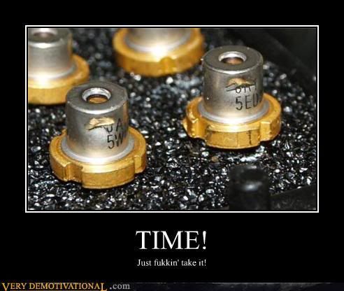
Time.jpg


awlego

0
Joined
Oct 9, 2009
Messages
160
Points
0
Take note that lm317's case is the same as the output pin - so don't attach it to the same heat sink as your laser without something electrically insulating!
 

alf638

0
Joined
Dec 10, 2010
Messages
218
Points
0
Really Embarrasing, but with my first harvest I only read one guide and it didn't have pictures, sure I knew what an LD looked like but not very well... Well i took apart the burner (at least I got it for free), took out the sled and then the diode holder. I then preceded to use a screwdriver to take apart the actual laser diode!!!
 
Joined
Dec 25, 2009
Messages
140
Points
0
I fried my diode again. Probably the 3rd diode I've fried in my whole history. Only one was not fried and that one died from being overdriven or soemthing. I connected the diode incorrectly after making an adjustment to my breadboard diode driver - It was connected to receive voltage out instead of current out, basically. Thought it was connected properly, started turning up the 'current' on the pot not realizing diode was just seeing voltage. cranked it up to like 12 V. diode dead. *sigh* Was a 445nm too.
 
Joined
Feb 5, 2008
Messages
6,252
Points
83
I fried my diode again. Probably the 3rd diode I've fried in my whole history. Only one was not fried and that one died from being overdriven or soemthing. I connected the diode incorrectly after making an adjustment to my breadboard diode driver - It was connected to receive voltage out instead of current out, basically. Thought it was connected properly, started turning up the 'current' on the pot not realizing diode was just seeing voltage. cranked it up to like 12 V. diode dead. *sigh* Was a 445nm too.
What was your powersource?

I am not sure I understand how you actually set all that up, would you mind sending some pictures?
 
Joined
Dec 25, 2009
Messages
140
Points
0
What was your powersource?

I am not sure I understand how you actually set all that up, would you mind sending some pictures?

A computer power supply for now since I haven't put together my own in a box yet.

Anyway, I had mistakenly connected the + terminal of the diode to the junction where my resistors and my potentiometer connect.
I can get photos yeah. but a schematic would be easier.
 
Joined
Feb 5, 2008
Messages
6,252
Points
83
A computer power supply for now since I haven't put together my own in a box yet.

Anyway, I had mistakenly connected the + terminal of the diode to the junction where my resistors and my potentiometer connect.
I can get photos yeah. but a schematic would be easier.
Any will do fine, yes. Computer power source? Ahh, well then I'm almost sure it's dead, but I have to make sure again.
 
Joined
Nov 10, 2008
Messages
4,186
Points
63
I had 2 445nm diodes screwed. One had its pins bent and broken while assembling everything in a c6 aurora host and the other one was a victom of the capacitor of a flexdrive :( I forgot to short it and when i hooked the diode on the driver i saw some smoke coming out of the host lol.
 
Joined
Feb 5, 2008
Messages
6,252
Points
83
I had 2 445nm diodes screwed. One had its pins bent and broken while assembling everything in a c6 aurora host and the other one was a victom of the capacitor of a flexdrive :( I forgot to short it and when i hooked the diode on the driver i saw some smoke coming out of the host lol.
That's NOT the result of capacitor charge. If your diode would be dead from capacitor charge, you would not even know it. Smoke was some connection in the driver board that was not meant to be there.

You might want to correct your other post also.
 
Joined
Feb 5, 2008
Messages
6,252
Points
83
I'm not sure what's that R4 doing there but you have connected it properly. Remove the R4 and your schematic is correct.

I am not sure you have wired everything correctly though.

Also, instead of the potenciometers, use a fixed resistor to set current. Much more safer that way.
 

HIMNL9

0
Joined
May 26, 2009
Messages
5,318
Points
0
^ sorry, no ..... in that schematic, R4 is in serie with the potentiometer, so it's part of the current limiting network ..... the LD is connected between the "out" and the GND (that there is not drawed)
 
Joined
Dec 25, 2009
Messages
140
Points
0
I'm not sure what's that R4 doing there but you have connected it properly. Remove the R4 and your schematic is correct.

I am not sure you have wired everything correctly though.

Also, instead of the potenciometers, use a fixed resistor to set current. Much more safer that way.

No, the schematic is correct. As I said I, in a rush, connected LD+ to the wrong place (where the arrow is pointing) and didn't realize it as I was cranking the pot, which ended up sending ~11.5V or 2.4A through the LD

Worst part is - I only had the LD in my possession a little over 24 hours. That's right, I fried it a few hours ago ;_;
 
Last edited:
Joined
Feb 5, 2008
Messages
6,252
Points
83
My bad , guys. Just seemed very weird that somebody would connect it that way, you can just use fixed resistance and call it a day. And a laser, not dead diode. If you were to do that right away, you'd have a beautiful working laser right now, no measurements, no trimming, no current setting.

Nice neat and clean.

Just my two cents. Trimmers in DDL drivers suck.
 
Joined
Dec 25, 2009
Messages
140
Points
0
My bad , guys. Just seemed very weird that somebody would connect it that way, you can just use fixed resistance and call it a day. And a laser, not dead diode. If you were to do that right away, you'd have a beautiful working laser right now, no measurements, no trimming, no current setting.

Nice neat and clean.

Just my two cents. Trimmers in DDL drivers suck.

Nah. I want adjustable output. Otherwise I would have just one resistor and no potentiometer.

PS. is 1.5A too high to drive the 445nm diodes? what about 1.3A?
 
Last edited:


Top