- Joined
- Feb 25, 2010
- Messages
- 1,643
- Points
- 113
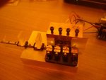
Well....Humph....LSG/LS...." Even a Blind Dog finds a Bone "....now and then !!! I thought having the beam off centre as it passes thru the C-lens / Plano Concave might give us some problems ??
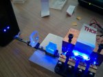
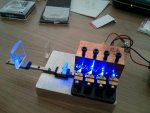
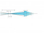
So.....If we rotate the LD's.... from llll to ---- AND rotate the C-Lens set..... 90 degree
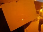
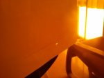
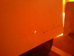
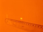
All four (4) beams will propagate into the Plano Concave lens....on centre .... and we end up with our (4) beams.....side by side ..... looking like this
[ ] [ ] [ ] [ ]
Four (4) almost square- rectangles.....side by side....But....alas....NOT a " Beam on Beam " arrangement !! Not all four (4) beams....superimposed over one another !!
Hmmmm...." Twist and Shout "
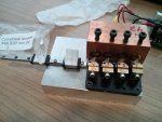
I have an idea on how to do this....with two (2) NUBM044 and two (2) NUBM07E.....not easy....not inexpensive...but...maybe could be done ?????????? Maybe even in a Hand Held format....maybe not ???
Who is up for 20W "o" Blue....ALL in One beam.... Mooohahahaha !!! ( There will be a discount offered if you like " Zippy the Clown " !!!!! )
CDBEAM
So.....If we rotate the LD's.... from llll to ---- AND rotate the C-Lens set..... 90 degree
All four (4) beams will propagate into the Plano Concave lens....on centre .... and we end up with our (4) beams.....side by side ..... looking like this
[ ] [ ] [ ] [ ]
Four (4) almost square- rectangles.....side by side....But....alas....NOT a " Beam on Beam " arrangement !! Not all four (4) beams....superimposed over one another !!
Hmmmm...." Twist and Shout "
I have an idea on how to do this....with two (2) NUBM044 and two (2) NUBM07E.....not easy....not inexpensive...but...maybe could be done ?????????? Maybe even in a Hand Held format....maybe not ???
Who is up for 20W "o" Blue....ALL in One beam.... Mooohahahaha !!! ( There will be a discount offered if you like " Zippy the Clown " !!!!! )
CDBEAM


") Sorry, I am not a millionaire like Ironman doing his builds in movies.
Sorry, I am not a millionaire like Ironman doing his builds in movies.