Welcome to Laser Pointer Forums - discuss green laser pointers, blue laser pointers, and all types of lasers

LPF Donation via Stripe | LPF Donation - Other Methods

Links below open in new window

ArcticMyst Security by Avery

Use a momentary / tactile button, as a latching switch - circuit?

rhd

0
Joined
Dec 7, 2010
Messages
8,475
Points
0
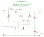
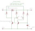
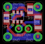
I'm looking for the smallest possible circuit that will allow a low current momentary button to operate as a high current latching (ie, on/off) toggle switch. In other words, it's more than just driving a MOSFET, the circuit needs to flip between on / off states.

There are a number of approaches online, but I'm hoping for one that draws no quiescent (standby) current. Failing that, I'm just looking for minimal part count.

Any suggestions?


Joined
Dec 11, 2011
Messages
4,364
Points
83
What you're looking for is a bistable flip flop to drive a MOSFET. There are both discrete BJT and IC designs (like using a 555). It's also called a power latch as when it's used to outsource the power line switching to a FET instead of a mechanical switch. There's always quiescent current being drawn in the off state unfortunately, but it can be kept to a minimum through good design.


Sent from my iPhone using Tapatalk
 

djQUAN

0
Joined
May 27, 2013
Messages
1,154
Points
63
What's your supply voltage? I have used those cheapie keychain lights that use a momentary tact switch to turn an LED on or off with a chip on board circuit that runs off of 3 button cells.

I just took out the PCB, trim it to size and use a switching device (mosfet, relay etc) that can handle the current.
 

rhd

0
Joined
Dec 7, 2010
Messages
8,475
Points
0
What's your supply voltage? I have used those cheapie keychain lights that use a momentary tact switch to turn an LED on or off with a chip on board circuit that runs off of 3 button cells.

I just took out the PCB, trim it to size and use a switching device (mosfet, relay etc) that can handle the current.

6V to 8.4V

I looked at bistable flip flops, but it doesn't seem like there are any ICs that run on my supply voltage, or for that matter, don't require 3 or 4 external components in addition to the MOSFET.
 

djQUAN

0
Joined
May 27, 2013
Messages
1,154
Points
63
That's a little high. Not sure what parts you have access to but if it were me, I would use a CMOS regulator (which draws nearly no quiescent current with no load, Torex and the like have a bunch of types) to drop the supply down for the COB flip flop then use a FET as a power switch.
 
Joined
Dec 11, 2011
Messages
4,364
Points
83
IIRC Dave from the EEVBlog did a video of a fully discrete power latch with very low quiescent current and a wide operating voltage, it might be worth looking in to. I don't know that you'll find a monolithic (chip + add a FET) solution though. You would think there would be one, but I haven't seen one used nor referenced so far.

Again, I always used a 555 for this until I went and moved on to using a uC for this kind of thing.
 
Joined
Jan 7, 2007
Messages
6,309
Points
83
You can also use an On/Off switch from RatShack (if any are open yet)
to drive the Mosfet. Use some resistance to ground for reliable shutoff.
HMike
 

Fiddy

0
Joined
May 22, 2011
Messages
2,726
Points
63
a SCR will latch on until A) it drains the the source voltage below its holding current or B) u remove the batteries :D
 

rhd

0
Joined
Dec 7, 2010
Messages
8,475
Points
0
IIRC Dave from the EEVBlog did a video of a fully discrete power latch with very low quiescent current and a wide operating voltage, it might be worth looking in to.

I just started watching this video. I was about to get really frustrated because it's 17 minutes long, and I just wanted the "bottom line".... but this guy won me over when he held up a whiteboard with the requirements:

1) Zero power when off
2) One on/off switch
3) Standalone (no micro controller)
4) Jellybean parts only
5) Minimal parts

I'm SOLD!

What do you guys think of this circuit? I'm going to create a board now. I'm happy to share the final board with the forum.

attachment.php


To see the video referenced above, take a look here:
https://www.youtube.com/watch?v=Foc9R0dC2iI
 

Attachments

  • SCHEMATIC.png
    SCHEMATIC.png
    19.2 KB · Views: 6,125
Last edited:

ARG

0
Joined
Feb 27, 2011
Messages
6,772
Points
113
The only problem I see is that the units on your capacitor are Henries :p
 

rhd

0
Joined
Dec 7, 2010
Messages
8,475
Points
0
The only problem I see is that the units on your capacitor are Henries :p

Watch out, or I'm going to come hunt you down with my 2,000 MW laser. It's really powerful because the driver supplies 2400 mAh of current. ;)

Okay, here we go. It's a 1cm square latching circuit. I'm going to order some up tonight. Total part cost is under $2.

attachment.php


attachment.php
 

Attachments

  • SCHEMATIC.png
    SCHEMATIC.png
    16.3 KB · Views: 4,179
  • board.png
    board.png
    26 KB · Views: 1,702
Last edited:
Joined
Feb 25, 2010
Messages
1,643
Points
113
MMMMmmmmm???? Maybe I will use one of these very small units in the Dragon's Head Red ???????? Very small....and unique !!!! Will this handle the current from two (2) 18650 LiPo....at 7.4 VDC ????? THANK YOU.

Lite'em up CDBEAM=======>
 

rhd

0
Joined
Dec 7, 2010
Messages
8,475
Points
0
Will this handle the current from two (2) 18650 LiPo....at 7.4 VDC ????? THANK YOU.

I don't know... you asked me if it will handle the current from your setup, and then proceeded to tell me everything except what that current is ;)
 
Joined
Dec 11, 2011
Messages
4,364
Points
83
You can use this circuit to control a pass FET of your choice for high power applications by adding one resistor and your pass FET.

RHD, this is the EEVBLOG board right? Let me know how much these boards cost, I'll definitely buy at least one from ya.
 

rhd

0
Joined
Dec 7, 2010
Messages
8,475
Points
0
You can use this circuit to control a pass FET of your choice for high power applications by adding one resistor and your pass FET.

RHD, this is the EEVBLOG board right? Let me know how much these boards cost, I'll definitely buy at least one from ya.

Sure thing! But I wouldn't charge ya for it. Just remind me in two months, lol, Oshpark takes months of lead time to arrive here in Canada ;)

Or would you prefer I just give you the brd files?

I wasn't planning to sell these, just figured I'd release the schematic / board open source once tested. It's basically the EEVBLOG circuit. I chose a 4A MOSFET (I think - not on my pc right now), and used a dual NPN IC, but otherwise it's basically the same circuit.


Top