Welcome to Laser Pointer Forums - discuss green laser pointers, blue laser pointers, and all types of lasers

LPF Donation via Stripe | LPF Donation - Other Methods

Links below open in new window

ArcticMyst Security by Avery

Three (3 ) Axis Adjustable LD Mount

Joined
Feb 25, 2010
Messages
1,643
Points
113
Well...I concluded that this LD mount deserved a separate thread !
!! See attached : THP-CDB-V6 drawing.

The design was greatly inspired by Trinh H P

The design builds on previous proposed designs and has not been built yet.

A Proof of Concept will be done.

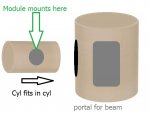
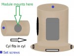
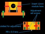
The LD mount uses two (2) rotating cylinders. A 12mm CU module w/LD....is set within an 18mm rotating collar @ 90 degree.

For Pitch adjustment, an 18mm collar is positioned within the main mount body. This collar is then positioned/rotated....up/down... to adjust to the perfect Pitch. Once the pitch is set.... a clamping bolt is tightened to fix the position and provide the best possible heat transfer between the collar and the main mount body.

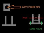
For LD Rotational alignment, the 12 mm module is positioned/rotated within the 18 mm collar unit. Once the Rotation is set...a set screw that is aligned with the 18 mm collar axis is tightened...and the rotational alignment is fixed.

Finally, for Yaw adjustment, the main mount body will be bolted to a standard Base/slotted foot plate which can be shifted left/right to achieve the best Yaw alignment. Once aligned....Fix the bolts to secure.

We have finally covered all the required degree's of movement for an LD mount...in hopefully the smallest and most simple design possible

All components will be Copper. I will machine the first unit within the next 30 days.

Thanx to all that have pushed the envelope so far !!

Drawing now attached.

CDBEAM :wave::wave::wave:
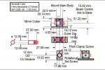
 

Attachments

  • THP-CDB V6.JPG
    THP-CDB V6.JPG
    103.5 KB · Views: 59
Last edited:


Joined
Jul 10, 2015
Messages
9,907
Points
113
This is what I see in my minds eye,it should have good heat transfer, both cylinders can rotate for vertical and horizontal adjustment and the module keeps its rotational alignment. It will need a bracket to lock it down and set screw to lock the inner cylinder as well as set screw to lock the module in place.

Main cylinder will need a portal both sides.


---edit---
The main cylinder could have a lip around it's base with slotted holes for attachment to the optics bed with cap head screws/washers.

This will also let the whole thing be positioned left to right, but the module/beam height will need to match the beam expander height., any small adjustment to true the beam should not changer the beam height enough to matter.


60973d1532244287-three-3-axis-adjustable-ld-mount-2cylmount.jpg


60975d1532249045-three-3-axis-adjustable-ld-mount-2cylmount2b.jpg
 

Attachments

  • 2cylmount.JPG
    2cylmount.JPG
    75.8 KB · Views: 105
  • 2cylmount2b.JPG
    2cylmount2b.JPG
    81.2 KB · Views: 101
Last edited:
Joined
Jul 10, 2015
Messages
9,907
Points
113
It's just an idea, anyone can offer improvements or a better idea and I have not seen CDBEAM777's drawing yet, I want to note that putting the set screw in from the flat of the smaller cylinder allows the diode module to be removed/turned without removing the small cylinder so it would be the best place for it IINM.

There's also the size, the diode module could be omitted and the small cylinder could be made to hold the diode and threaded for our G2 lens, wires exit a 2nd portal on the back. The small cylinder could have flat grooves milled out on each side and tapped for the G2 lens and have a seat cut from the back for the diode, a hollow plug could thread in to retain the diode, this way the whole thing can be physically smaller.
 
Last edited:
Joined
Feb 25, 2010
Messages
1,643
Points
113
Hmmm...I will think on this alternate variation. The basic Trinh concept..." cylinder within a cylinder " remains.

A clamping arrangement to secure the inner 18mm collar....should provide increased surface to surface contact....which in turn will increase thermal transfer across the interface from the 18 mm collar to Main Mount body. Of course, wicking away the LD heat is always preferred.

OK....as far as reducing the size of the inner LD mount.....well....I am basically a lazy person....and prefer to take the path of least work. Even if we use a custom inner cylinder....I think we will gain little size reduction....and have more work. For me....use what is on the shelf !!….when possible.

As I have said in the past....always use what is made in mass volume....if it makes sense...like the 12mm CU module. When we use a purchased piece, we take advantage of uniform geometry from piece to piece, reduced work , and….a good unit at a volume cost. Perfect.

I also believe the 12mm CU module will need a slight modification. That would be to very slightly open up the LD flange seat ID. This then will provide a friction fit vs. a press fit. When the Module is screwed together, with the LD positioned within, the raised dias on the module back unit comes in tight contact with the LD back...and that is where a major amount of heat is present. I have blah, blah'ed on B4 about why I strongly prefer a friction fit vs. a press fit...proper alignment being the main reason.

Anyway....my thoughts for now ! :D:D

CDBEAM
 
Last edited:
Joined
Jul 10, 2015
Messages
9,907
Points
113
The larger cylinder in my drawing can be square, there's no real need for it to be round, just the inner cylinder.

Also it could be a bracket with a cube in it's forks like this.

As long as the forks are thick enough heat should be wicked away just fine once the cube is adjusted and tightened down, the base can be turned and should have slotted mounting holes, it's just like the square mounts with the mounting flange at the base only the cube can tilt so it's fully adjustable.

60979d1532267620-three-3-axis-adjustable-ld-mount-2axiscure3.jpg
 

Attachments

  • 2axiscure3.JPG
    2axiscure3.JPG
    62.5 KB · Views: 92
Last edited:
Joined
Feb 25, 2010
Messages
1,643
Points
113
Hmmmmm ????? " Inboard " ( THP-CDB) vs. " Outboard " ( RC Concept )….Hmmm....Both would likely work !!

...Hmmmmm ??? Some determining considerations;

* Over all size...including unit height, needs to be a small as possible !
* Overall cost, low as possible.
* Ease of adjustability.
* Best thermal transfer properties.
 
Last edited:
Joined
Jun 25, 2017
Messages
351
Points
63
I would suggest to use two set screws to be able to choose which one (or both) is used. In addition I had great success with spring ball plunger set screws. The allow to do the final adjustment under spring tension so nothing slips away.

Singlemode
 
Joined
Feb 25, 2010
Messages
1,643
Points
113
I would suggest to use two set screws to be able to choose which one (or both) is used. In addition I had great success with spring ball plunger set screws. The allow to do the final adjustment under spring tension so nothing slips away.

Singlemode

Well...I think a set screw....or two....will be the only option to fix the 12mm CU module within the 18mm Pitch adjusting collar.

The goal is to machine the absolute tightest tolerance between the two sections.... so as to maximize thermal transfer.

So.... a spring pocket could be used...or a set screw with a spring feature could come in from the other side....centered in the 18mm axis.....surly !!!

So...we keep refining the concept....all hands on deck.....Thanx !!!
Multimode input from any/all members....is just a winner !!

CDBEAM :p:p
 
Joined
Sep 20, 2013
Messages
17,438
Points
113
In reality, how far off pitch and yaw could the diode be because of a bad fit? It looks like these adjustment go much farther than they need to. This will introduce heat transfer problems, IMO. If the press is off, it can't possibly be off by that much. :thinking:
 
Joined
Jul 10, 2015
Messages
9,907
Points
113
In reality, how far off pitch and yaw could the diode be because of a bad fit? It looks like these adjustment go much farther than they need to. This will introduce heat transfer problems, IMO. If the press is off, it can't possibly be off by that much. :thinking:


Chris used a 20mm module and it was off pretty far, I just ordered a 20 to 12 heat sink from Rich so I will try a 12mm module and see.

Screen_Shot_2018_07_14_at_8_50_30_PM.png


HEAT SINK LINK:
https://laserpointerforums.com/f39/...us-adapters-lasers-100082-74.html#post1540288


60984d1532293670-sale-thread-hosts-heat-sinks-focus-adapters-lasers-fullsizeoutput_870.jpeg


The square copper block holding the 12mm module won't need to adjust very much, it could pivot just a couple of mm above the copper bracket, what ever puts the beam height even with the beam expander center to center,also a set screw could be drilled and tapped into each corner ( or just 2 diagonally ) to help fine adjustment, this could be made pretty small.

NOTE: The red pivot screws will be tightened down after adjusting for vertical alignment, that should make for a good heat transfer through the thick copper side brackets.

60990d1532301199-three-3-axis-adjustable-ld-mount-xymount2c2b.jpg
 

Attachments

  • xymount2c2b.JPG
    xymount2c2b.JPG
    94.5 KB · Views: 96
Last edited:
Joined
Feb 25, 2010
Messages
1,643
Points
113
In reality, how far off pitch and yaw could the diode be because of a bad fit? It looks like these adjustment go much farther than they need to. This will introduce heat transfer problems, IMO. If the press is off, it can't possibly be off by that much. :thinking:


Well....IMNSHO....the " Press " install method sucks. By evolving to a friction fit....maybe, maybe 99% of the problems go away ???? Fine....That is very welcome….but....I am somewhat doubtful....

I have fought with alignment issues....for countless hours....and have concluded....a mount that has Pitch and Yaw adjustability....will be a great addition.

It takes very, very little to off-axis the beam....and the Beam Expander is a real demanding unit. Combine the two....and maximum adjustability is desirable.

OK....All....get to assemble !!! The real truth lies there. Good Luck ! I will machine a Proof of Concept....regardless.....and put this on the shelf....If needed....it will be there !!

CDBEAM :san::san::san:
 
Last edited:
  • Like
Reactions: GSS
Joined
Sep 20, 2013
Messages
17,438
Points
113
When I was talking about a press fit, it was in a 12 mm module, not a 20 mm module. I have to intention of using that module at all. If the module from Rich is made to seat the 12 mm module square with the bench, how far off could that be? A fraction of a degree? Having a pivot that allows for 15 or more degrees of adjustment seems like it could be unnecessary.
 
Joined
Jul 10, 2015
Messages
9,907
Points
113
Try it and see, you can't cheat anything out of the C-lens pair, they must align with the beam, so if the beam is not centered and you don't care about a beam expander then you can choose to live with it, but if you want to use a beam expander that centers in your host then your starting beam will have to be centered within in the host, within reason and " reason is what will work " it's pretty picky, but maybe making the 12mm module friction fit and relying on the ring pedestal in the full copper back half will do the trick, try and see, if not then you can go the next step.

You may get a far field spot with a slight skew and decide you can live with it, actually the 3.3XBE can develop some thread slack, I find some are better fit than others.....also if you aim for perfection and fall short your end result will typically be better than if you aim for ok and fall short.
 
Last edited:
Joined
Dec 9, 2011
Messages
221
Points
28
I follow these threads because I really love mechanics and new ways to do things. I'm trying to wrap my head around the need for pitch adjustment though? Can someone explain?


Top