Welcome to Laser Pointer Forums - discuss green laser pointers, blue laser pointers, and all types of lasers

Buy Site Supporter Role (remove some ads) | LPF Donations

Links below open in new window

FrozenGate by Avery

Three (3 ) Axis Adjustable LD Mount

Have you ever aligned cylindrical lens pairs to reduce a MM diodes divergence ?

----edit----
 
Last edited:


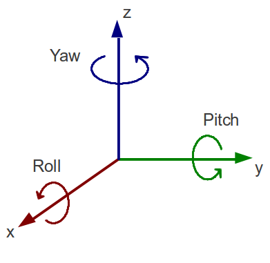
In the vertical axis, the pitch is the angle that the axis is off. The yaw is how much the horizontal axis angle is off.
 
I'm not getting started on defining pitch and yaw as it could relate to laser alignment, the're aviation terms.

I'm going to call it horizontal and vertical, you call it whatever you want. :beer:

Horizontal and vertical are really obvious, as you stand behind your laser horizontal is left and right, while vertical is up and down.


It's like telling someone which tail light is out left or right....well it depends on where you're standing, in front of the car or in back....I just say drivers side and passenger side, it's hard to misunderstand and some people will just flat out know that right is always the drivers side while someone else will swear right is for certain the passenger side.

Pitch and yaw are terms used to describe flight, they are not really laser specific as far as I know.

rollPitchYaw.png


While the yaw is perpendicular to the body of wings, the pitch axis is perpendicular to the yaw axis and parallel to the body of wings. In flight or the state of aircraft is in air, certain parts of the aircraft produce yawning motion and pitch motions.

•Rotation around the front-to-back axis is called roll.
•Rotation around the side-to-side axis is called pitch.
•Rotation around the vertical axis is called yaw.
 
Last edited:
Have you ever aligned cylindrical lens pairs to reduce a MM diodes divergence ?

Yes, lots actually.

Imagine doing that in a hand held build that incorporates a beam expander and you will understand why the starting beam needs to be centered to match the beam expander, like I said if not using the beam expander and your corrected beam were to exit 2 degrees off center it might not be noticed, but fed into a beam expander that's attached to the host with a difference in alignment and you will see it.

A few things can cause the beam to exit off axis.

A. The collimator lens could have some degree of tip or tilt. Good machining can solve this problem.

B. The most common is the emitter is not concentric relative to the lens. This can be solved by shifting the diode X or Y relative the lens.

C. The die is actually misaligned with the diode body. Most spec sheets give the max degree of misalignment allowed. Centering the diode to the lens will make the beam exit straight just displaced by some amount.

Almost all beam alignment issues can be solved by just moving the diode X or Y.
 
Last edited:
Another nice thing about using a mount like this is if you go back later to replace your laser diode you can likely realign the beam to your glued in place C-lenses.

You won't need to hand fit a mount and/or re-glue C-lenses.

60990d1532301199-three-3-axis-adjustable-ld-mount-xymount2c2b.jpg
 
Last edited:
Yes I use a razor blade and carefully work at it, it is hard to get all the glue off the lens once removed, that's one reason I tried gluing the lenses to little aluminum squares, that way I could remove and reuse them easier.

If you have glue that's hard to remove after you have the lens free you can use them upside down.
 
Last edited:
A few things can cause the beam to exit off axis.

A. The collimator lens could have some degree of tip or tilt. Good machining can solve this problem.

B. The most common is the emitter is not concentric relative to the lens. This can be solved by shifting the diode X or Y relative the lens.

C. The die is actually misaligned with the diode body. Most spec sheets give the max degree of misalignment allowed. Centering the diode to the lens will make the beam exit straight just displaced by some amount.

Almost all beam alignment issues can be solved by just moving the diode X or Y.

First of all, the emitter is, for our purposes, a straight line and therefore, can't be concentric to anything. Concentricity concerns how one circle corresponds to another circle. If they aren't concentric, the they are eccentric. This is where some parts of the circles are not aligned to one another. Secondly, if the die is not centered in the focusing lens, this is not an angle adjustment, but a position adjustment. If it is close, and many are, then it makes little difference and the beam will exit the lens in the center, or close enough to it that it won't matter. These angle adjustments are in addition to position adjustments and should not be confused with position as you will soon have a mess in trying to align one with the other.
 
Last edited:
First of all, the emitter is, for our purposes, a straight line and therefore, can't be concentric to anything. Concentricity concerns how one circle corresponds to another circle. If they aren't concentric, the they are eccentric. This is where some parts of the circles are not aligned to one another.

I'm not trying to be a Dick here. Really. But, is everyone on this board a contrarian? It seems like many here want to argue for arguments sake not to learn anything new or advance our understanding.

---rant over---

Maybe Concentric is not the exact word. Maybe I should have used "coaxial" or "centered". Yes, Concentric usually means like objects centered around each other. It doesn't always have to be circular objects.

Secondly, if the die is not centered in the focusing lens, this is not an angle adjustment, but a position adjustment. If it is close, and many are, then it makes little difference and the beam will exit the lens in the center, or close enough to it that it won't matter. These angle adjustments are in addition to position adjustments and should not be confused with position as you will soon have a mess in trying to align one with the other.

Sorry "close" doesn't cut it with position alignment. Even the smallest amount off center will cause the beam to exit at an angle.

The beam may look like its exiting in the center of the lens. Its really not. However, unless you are stacking or knife edging many beams, the exits position may not matter. The beam angle offset from normal will for sure cause problems especially with more complex paths, as RC pointed out.

So, what I was trying to say in my first post was: the X,Y "position" of the die(LD) relative to the first lens can be manipulated to correct the angular offset of the beam. This simplifies the machining greatly.

In my builds I find the X,Y is the easiest to align and the rotation is always the hardest. The rotation needs to be very good to reduce aberrations in the cylinder lenses.

Here is the back of a 10X P73 combiner I was just prototyping. It worked pretty good. Rotation is still a bit finicky but can be done with some patience. On the plate that holds the diode I cut a slot and drilled two holes. The slot allows me to use a small pliers to set rotation and the holes allow a small screwdriver to "push" the diode left or right. This is all the adjustment needed to align 10 diodes with 6X cyl correction. Of course there are probably a million ways to do it. This example is just one.

https://photos.google.com/share/AF1QipMaeKEyOFe664QjNUIxccDudJtOyshEsZgZZ18Tb8kGKJz2Vx-bbPvyUqW3knSlFA?key=RXhrQjNRM1lJOW02NDRCbW5sWl9wN0hudVFVQllR
 
Last edited:
Hardly anyone gets the emitter exactly in the center of the focusing lens, so close is all one can hope for. It is called tolerance and is a measure of what you can get away with. And yes, in this case "close enough" can work as the exact center is basically unachievable. If your link is trying to show something you have not already stated, you need to fix it. I cannot see it. :thanks:
 
Hardly anyone gets the emitter exactly in the center of the focusing lens, so close is all one can hope for. It is called tolerance and is a measure of what you can get away with. And yes, in this case "close enough" can work as the exact center is basically unachievable. If your link is trying to show something you have not already stated, you need to fix it. I cannot see it. :thanks:


Link should work now. Hopefully.

If you put the emitter in the center then all the other work arounds to fix the pointing error are not needed. KISS principal.
 
My point is/was that the emitter can never be exactly centered, so being close to center, as in +/- 0.001 mm as just an example, might work fine. It is when the emitter is so far out of tolerances that you start having issues and need to compensate for it. I am trying to get a work around that involves a copper 12 mm module and a 20 mm copper heat sink that will be centered well enough to avoid having to deal with positions and angles. Only time will tell.
 
My suggestion for those that want to use correction optics, is to get away from the pressed in type mounts. A simple mount that allows the diode to "slide" X, Y on the rear face of the mount is all that's really needed. And .001mm resolution is easy with only "bare hands". This type mount is pretty standard in projectors. Maybe someone needs to make one for handhelds.
 
My suggestion for those that want to use correction optics, is to get away from the pressed in type mounts. A simple mount that allows the diode to "slide" X, Y on the rear face of the mount is all that's really needed. And .001mm resolution is easy with only "bare hands". This type mount is pretty standard in projectors. Maybe someone needs to make one for handhelds.

I highly doubt that a person can perform 0.001mm resolution with "bare hands" (though such precision is not needed anyway to align the relative diode-lens position). Making the diode movable in xy have to be designed in such way, that the heat transfer is still good enough for a handheld device.

Singlemode
 
HEY LOG, What is this supposed to be ?

This is the pic you linked, this shows nothing of any value related to the topic.

61008d1532401386-three-3-axis-adjustable-ld-mount-wtflogasshat.jpg
 

Attachments

  • WTFlogASSHAT.JPG
    WTFlogASSHAT.JPG
    114.5 KB · Views: 61
Last edited:
My suggestion for those that want to use correction optics, is to get away from the pressed in type mounts. A simple mount that allows the diode to "slide" X, Y on the rear face of the mount is all that's really needed. And .001mm resolution is easy with only "bare hands". This type mount is pretty standard in projectors. Maybe someone needs to make one for handhelds.

Only high-end lathes or CNC machines can reach a precision of 0.001mm, a hand is not possible
Maybe you wrong
 
I wonder if you can get it smaller to fit the smaller diameter modules. Now that would be neat :beer:


Back
Top